Ford Fusion: Driveshaft / Rear Driveshaft. Removal and Installation
Special Tool(s) / General Equipment
| Flat-Bladed Screwdriver | |
| Punch | |
| Copper Hammer |
Removal
NOTE: The max articulation of any CV is 10 degrees. The max articulation of any U-joint is 12 degrees. If the CV or any U-joint of the driveshaft is articulated further then the max allowable degrees damage may occur.
NOTE: Removal steps in this procedure may contain installation details.
-
Remove the muffler and tailpipe.
Refer to: Muffler and Tailpipe (309-00A Exhaust System - 1.5L EcoBoost (118kW/160PS) – I4, Removal and Installation).
Refer to: Muffler and Tailpipe (309-00C Exhaust System - 2.5L Duratec (125kW/170PS), Removal and Installation).
Refer to: Muffler and Tailpipe (309-00D Exhaust System - 2.7L EcoBoost (238kW/324PS), Removal and Installation).
Refer to: Muffler and Tailpipe (309-00B Exhaust System - 2.0L EcoBoost (184kW/250PS) – MI4, Removal and Installation).
-
If equipped.
Remove the retainers and the underbody shield.
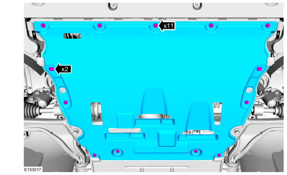 |
-
If equipped.
Remove the retainers and the front air deflectors.
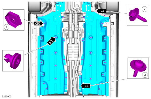 |
-
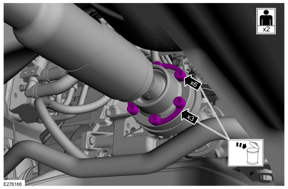
NOTE: The installation step requires the aid of another technician.
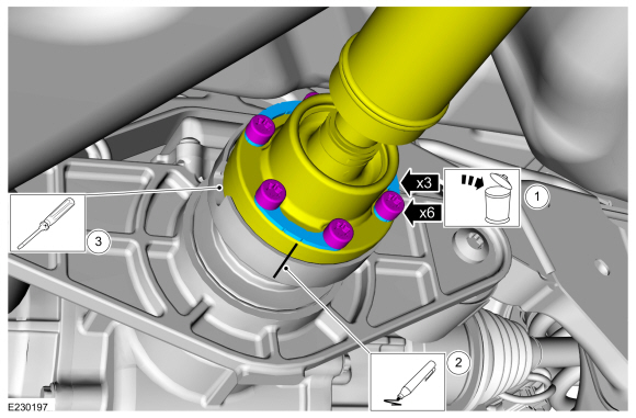
Remove and discard the driveshaft to PTU bolts and the retaining straps.
Torque: 26 lb.ft (35 Nm)
 |
-
Separate the driveshaft from the PTU flange.
-
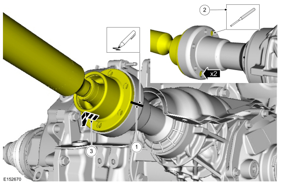
NOTE: Make sure that the component aligns with the installation mark.
Index-mark the driveshaft and PTU flange.
-
NOTICE: Do not remove driveshaft from the PTU flange by pulling on the driveshaft tube. Damage to the CV-joint can result.
NOTE: This is a tight fit, do not remove the CV flange from the PTU flange at this time.
Using general equipments, separate the driveshaft from the PTU flange.
Use the General Equipment: Punch
Use the General Equipment: Copper Hammer
-
Remove the driveshaft from the PTU flange.
-
 |
-
Separate the driveshaft from the drive pinion flange.
-
Remove and discard the driveshaft to RDU bolts and the retaining straps.
Torque: 26 lb.ft (35 Nm)
-
NOTE: Make sure that the component aligns with the installation mark.
Index-mark the driveshaft and RDU flange.
-
NOTICE: Do not remove driveshaft from the pinion flange by pulling on the driveshaft tube. Damage to the CV-joint can result.
NOTE: The driveshaft to drive pinion flange is a tight fit and will not come apart until the rear differential is removed.
Using a general equipment, separate the driveshaft from the drive pinion flange.
Use the General Equipment: Flat-Bladed Screwdriver
-
Remove and discard the driveshaft to RDU bolts and the retaining straps.
 |
-
NOTICE: Do not over articulate the driveshaft or damage may occur.
NOTICE: The driveshaft is long and heavy with multiple U-joints. The help of a assistant will be needed. Do not over articulate the driveshaft or damage may occur.
NOTE: The max articulation of any CV is 10 degrees. The max articulation of any U-joint is 12 degrees. If the CV or any U-joint of the driveshaft is articulated further then the max allowable degrees damage may occur.
-
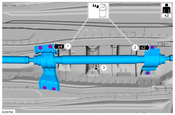
Remove and discard the rear center bearing bracket bolts.
Torque: 22 lb.ft (30 Nm)
-
Remove and discard the front center bearing bracket bolts.
Torque: 41 lb.ft (55 Nm)
-
NOTE: When installing the driveshaft, it will be necessary to place the CV joint flanges of the driveshaft into the PTU and RDU flanges before installing the center bearing bolts.
With an assistant remove the driveshaft.
-
Remove and discard the rear center bearing bracket bolts.
 |
Installation
-
NOTE: If a driveshaft is installed and driveshaft vibration is encountered after installation, index the driveshaft.
To install, reverse the removal procedure.
 Driveshaft Angle Measurement. General Procedures
Check
NOTE:
This procedure does not apply to CV joints, flex couplers or
double cardan joints that are used in some driveshafts. This check is
for single-cross and roller-style joints found in the driveshafts...

Other information:
Ford Fusion 2013–2020 Service Manual: Luggage Compartment Lid Release Switch. Removal and Installation
Removal Remove the luggage compartment lid moulding. Refer to: Luggage Compartment Lid Moulding (501-08 Exterior Trim and Ornamentation, Removal and Installation). Release the luggage compartment lid release switch. Installation To install, reverse the removal procedure. ..
Ford Fusion 2013–2020 Service Manual: Clockspring. Removal and Installation
Removal NOTE: Removal steps in this procedure may contain installation details. WARNING: Turn the ignition OFF and wait one minute to deplete the backup power supply. Ignition must remain OFF until repair is complete. Failure to follow this instruction may result in serious personal injury or death in the event of an accidental deployment. If a SRS fault is present, con..
Categories
- Manuals Home
- 2nd Generation Ford Fusion Owners Manual
- 2nd Generation Ford Fusion Service Manual
- Traction Control
- Memory Function
- Powertrain
- New on site
- Most important about car
Understanding Your Tire Pressure Monitoring System
The tire pressure monitoring system measures pressure in your road tires and sends the tire pressure readings to your vehicle. You can view the tire pressure readings through the information display. The low tire pressure warning light will turn on if the tire pressure is significantly low. Once the light is illuminated, your tires are under-inflated and need to be inflated to the manufacturer’s recommended tire pressure. Even if the light turns on and a short time later turns off, your tire pressure still needs to be checked.