Ford Fusion: Parking Brake and Actuation / Parking Brake - System Operation and Component Description. Description and Operation
System Operation
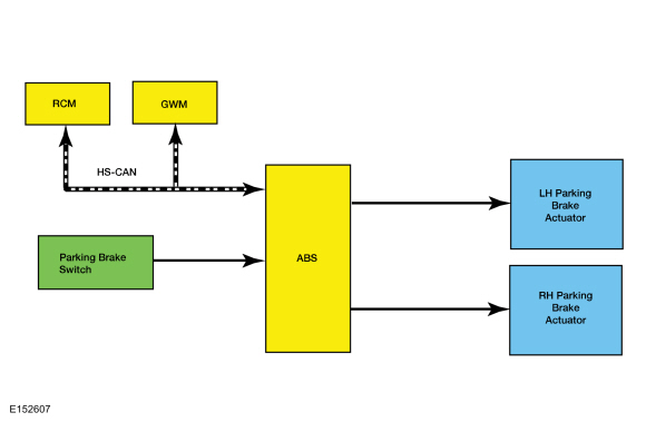
System Diagram
Network Message Chart
NOTE: The TCM is also known as the Secondary On Board Diagnostic Module C (SOBDMC).
Module Network Input Messages - ABS Module
| Broadcast Message | Originating Module | Message Purpose |
|---|---|---|
| Accelerator pedal position | PCM | This message is sent to the GWM and then to the ABS module. This message informs the ABS module of the current position of the accelerator pedal, 0-100%. |
| Brake on-off switch | PCM | This message is sent to the GWM and then to the ABS module. This message informs the ABS module the driver has pressed the brake pedal. |
| Clutch pedal position | PCM | This message is sent to the GWM and then to the ABS module. This message informs the ABS module the driver has pressed the clutch pedal. |
| Driven wheel propulsion torque | PCM | This message is sent to the GWM and then to the ABS module. This message provides the ABS module of the current amount of propelling torque being applied to the driven wheels by the engine or electric motor. |
| Driver door ajar status | BCM | This message is sent to the GWM and then to the ABS module. This message informs the ABS module the driver door status, closed or open. |
| Driver seat belt buckle status | RCM | This message informs the ABS module of the current status of the driver seat belt buckle; buckled, unbuckled, faulty or unknown. |
| Engine off time | PCM | This message is sent to the GWM and then to the ABS module. This message informs the ABS module how long, in seconds, the engine has been off. |
| Engine Revolutions Per Minute (RPM) | PCM | This message is sent to the GWM and then to the ABS module. This message informs the ABS module of the current engine Revolutions Per Minute (RPM). |
| Gear lever position | TCM | This message is sent to the GWM and then to the ABS module. This message informs the ABS module of the current gear selector lever position. |
| Ignition status | BCM | This message is sent to the GWM and then to the ABS module. This message informs the ABS module of the current ignition status; off, accessory, run, start, invalid or unknown. |
| Key in ignition status | BCM | This message is sent to the GWM and then to the ABS module. This message informs the ABS module of the current ignition key status; in or out. |
| Longitudinal acceleration | RCM | The ABS module uses this message to confirm forward or rearward vehicle movement. |
| Transmission in REVERSE | PCM | This message is sent to the GWM and then to the ABS module. This message informs the ABS module of the current reverse gear status; inactive or active. |
| Vehicle configuration data | BCM | This message is sent to the GWM and then to the ABS module. This message provides the ABS module with the current optional and configured items such as tire size, axle ratio, manual or automatic transaxle, keyless entry and VIN. |
Parking Brake and Actuation
The ABS module monitors and controls the parking brake system. The ABS module sends a reference voltage to the parking brake switch. When the driver moves the parking brake switch to the APPLY position, the reference voltage is sent back to the ABS module indicating an APPLY request. The ABS module then determines from sensor inputs if the parking brakes can be applied and sends voltage to the parking brake actuator motors. Once the parking brakes are fully applied, the ABS module sends a message to the IPC which illuminates the red BRAKE warning indicator. If the red BRAKE warning indicator is already illuminated due to a non-parking brake concern, the IPC displays PARK BRAKE APPLIED in the message center. When the driver moves the parking brake switch to the RELEASE position, the reference voltage is sent back to the ABS module indicating a RELEASE request. The ABS module then determines from sensor inputs and CAN messages (ignition state and brake pedal input) if the parking brakes can be released and sends voltage to the parking brake actuator motors. Once the parking brakes are fully released, the ABS module sends a message to the IPC which extinguishes the red BRAKE warning indicator. If the red BRAKE warning indicator cannot be extinguished due to a non-parking brake concern, the IPC displays PARK BRAKE RELEASED in the message center.
Automatic Release
The parking brakes are designed to automatically release under certain circumstances.
For vehicles equipped with an automatic transmission:
- the driver door must be closed.
- the engine must be running or the green Ready-to-Drive indicator must be illuminated.
- the transmission must be in any forward gear or REVERSE.
For vehicles equipped with a manual transmission:
- the driver door must be closed.
- the engine must be running.
- the clutch pedal must be pressed
Once all the conditions have been met, the parking brake releases automatically when the accelerator pedal is pressed. A vehicle driving away up an incline requires more accelerator pedal input than a vehicle driving away down an incline.
Service Mode
Service
mode is also known as maintenance mode. The parking brake system must
be placed in service mode to service the rear brake pads or when
removing rear brake components to service other components. The system
can be placed in service mode by using the diagnostic scan tool or by
following the steps in the EPB Service Mode Activation and Deactivation procedure.
Refer to: Electronic Parking Brake (EPB) Service Mode Activation and Deactivation (206-05 Parking Brake and Actuation, General Procedures).
Once the system is placed in service mode, the message center will
display MAINTENANCE MODE, the yellow parking brake indicator illuminates
and the parking brake system is deactivated. The only way to reactivate
the parking brake system is by correctly exiting service mode.
Disconnecting the vehicle battery will not reset the system or exit
service mode. If the vehicle is driven greater than 8 km/h (5 mph) while
in service mode, the yellow parking brake warning indicator is
illuminated, the red BRAKE warning indicator flashes and a warning chime
sounds.
Red Brake Warning Indicator
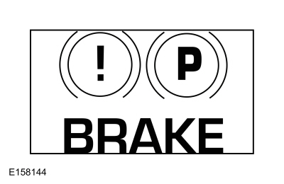
The red BRAKE warning indicator notifies the driver of hydraulic brake concerns, some ABS concerns and parking brake application. When a hydraulic brake or ABS
concern is present, the warning indicator illuminates solidly. After
the parking brakes are fully applied, the red BRAKE warning indicator
illuminates and remains illuminated as long as the ignition is set to
ON. If the ignition is set to OFF after the parking brakes are applied
or if the parking brakes are applied after the ignition is set to OFF
the red BRAKE warning indicator illuminates for 10 seconds and is then
extinguished.
Refer to: Instrument Panel Cluster (IPC) (413-01 Instrumentation, Message Center and Warning Chimes)
.
Yellow Parking Brake Indicator
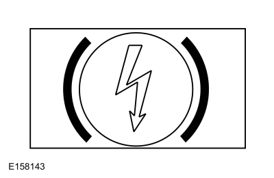
The
yellow parking brake indicator is used in conjunction with the message
center to notify the driver of parking brake system concerns. When a
concern or DTC is present,
the indicator illuminates and a message is displayed in the message
center. The yellow parking brake indicator also illuminates when the
parking brake system is in service mode.
Refer to: Instrument Panel Cluster (IPC) (413-01 Instrumentation, Message Center and Warning Chimes)
.
Component Description
Anti-Lock Brake System (ABS) Module
The ABS module is attached directly to the HCU and is the electronic control unit for the parking brake system. The ABS
module monitors all switch inputs, sensor inputs and High Speed
Controller Area Network (HS-CAN) messages that relate to the parking
brake system, then directly controls the parking brake actuator motors.
The ABS module also sets Diagnostic Trouble Codes (DTCs) in the event that a system or component failure should occur.
Refer
to: Anti-Lock Brake System (ABS) and Stability Control - Vehicles Built
Up To: 03-06-2013 (206-09 Anti-Lock Brake System (ABS) and Stability
Control)
.
Refer to: Anti-Lock Brake System (ABS) and Stability
Control - Vehicles Built From: 20-05-2013 (206-09 Anti-Lock Brake System
(ABS) and Stability Control)
.
Parking Brake Actuator Motor
The parking brake actuator motors are single speed reversible electric motors mounted on the rear brake calipers. The motors can be serviced separately from the calipers.
Parking Brake Switch
The parking brake switch is a 3 position switch with 2 sets of 3 internal micro switches, one set is for APPLY and one set is for RELEASE. The 3 switch positions are APPLY (pulled up), NEUTRAL (at rest or static) and RELEASE (pushed down).
Whenever the parking brake switch is disconnected and then reconnected, a DTC sets in the ABS module and the ABS module disables the parking brake system. To restore parking brake system functionality and to clear the DTC, the parking brake switch must be moved through all 3 positions twice within 5 seconds pausing for approximately one-half second when the switch is in the NEUTRAL position between each apply and release.
 Parking Brake - Overview. Description and Operation
Overview
The
parking brake system uses 2 switch activated, Electronic Control Unit
(ECU) controlled motors to apply and release the rear brake calipers...
 Parking Brake. Diagnosis and Testing
DTC Chart: Anti-Lock Brake System (ABS) Module
Diagnostics in this manual assume a certain skill level and knowledge of Ford-specific diagnostic practices...
Other information:
Ford Fusion 2013–2020 Owners Manual: Anti-Theft Alarm
The system will warn you of an unauthorized entry to your vehicle. It will be triggered if any door, the luggage compartment or the hood is opened without using the key, remote control or keyless entry keypad. The direction indicators will flash and the horn will sound if unauthorized entry is attempted while the alarm is armed...
Ford Fusion 2013–2020 Service Manual: Evaporative Emission Blocking Valve. Removal and Installation
Removal NOTE: Removal steps in this procedure may contain installation details. With the vehicle in NEUTRAL, position it on a hoist. Refer to: Jacking and Lifting - Overview (100-02 Jacking and Lifting, Description and Operation). Disconnect the EVAP canister quick connect couplings...
Categories
- Manuals Home
- 2nd Generation Ford Fusion Owners Manual
- 2nd Generation Ford Fusion Service Manual
- Electrical
- Traction Control
- Engine
- New on site
- Most important about car
Power Door Locks
The power door lock control is on the driver and front passenger door panels.