Ford Fusion: Fuel Tank and Lines - 1.5L EcoBoost (118kW/160PS) – I4 / Fuel Lines. Removal and Installation
Ford Fusion 2013–2020 Service Manual / Powertrain / Fuel System - General Information / Fuel Tank and Lines - 1.5L EcoBoost (118kW/160PS) – I4 / Fuel Lines. Removal and Installation
Removal
NOTE: Removal steps in this procedure may contain installation details.
-
Refer to: Gasoline and Gasoline-Ethanol Fuel Systems Health and Safety Precautions (100-00 General Information, Description and Operation). WARNING:
Before beginning any service procedure in this
section, refer to Safety Warnings in section 100-00 General Information.
Failure to follow this instruction may result in serious personal
injury.
WARNING:
Before beginning any service procedure in this
section, refer to Safety Warnings in section 100-00 General Information.
Failure to follow this instruction may result in serious personal
injury.
-
Remove the Fuel Tank.
Refer to: Fuel Tank (310-01A Fuel Tank and Lines - 1.5L EcoBoost (118kW/160PS) – I4, Removal and Installation).
-
-
Disconnect the brake lines.
Torque: 133 lb.in (15 Nm)
-
Disconnect the electrical connector and fuel line retainer.
-
Disconnect the brake lines.
 |
-
-
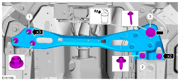
Remove the nuts.
Torque: 33 lb.ft (45 Nm)
-
Remove the bolts.
Torque: 44 lb.ft (60 Nm)
-
NOTE: Discard the specified component. Follow local disposal regulations.
Remove the bolt and the cross member.
Torque:
Stage 1: 76 lb.ft (103 Nm)
Stage 2: 270°
-
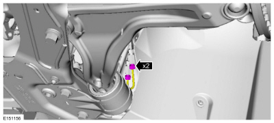
Remove the nuts.
 |
-
Disconnect the brake lines.
Torque: 133 lb.in (15 Nm)
 |
-
Remove the engine cover.
 |
-
Remove the Air Cleaner Outlet Pipe.
Refer to: Air Cleaner Outlet Pipe (303-12A Intake Air Distribution and Filtering - 1.5L EcoBoost (118kW/160PS) – I4, Removal and Installation).
-
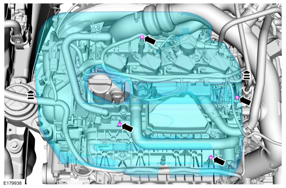
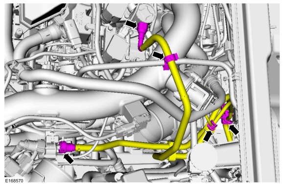
NOTE: Some residual fuel may remain in the fuel tubes after releasing the fuel system pressure. When disconnecting or removing any fuel tubes, carefully drain any residual fuel into a suitable container.
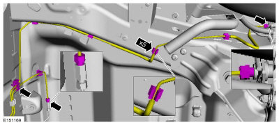
Disconnect the quick release couplings.
Refer to: Quick Release Coupling (310-00A Fuel System - General Information - 1.5L EcoBoost (118kW/160PS) – I4, General Procedures).
 |
-
-
Disconnect the fuel line retainer.
-
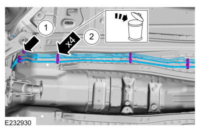
Disconnect and discard the fuel line retainers
attaching to underbody. Remove the fuel lines from the vehicle.
-
Disconnect the fuel line retainer.
 |
Installation
-
To install, reverse the removal procedure.
-
Bleed the brake system.
Refer to: Brake System Pressure Bleeding (206-00 Brake System - General Information, General Procedures).
 Fuel Tank and Lines - Overview. Description and Operation
Fuel System
NOTICE:
Repairs of the fuel system are to be achieved only by
replacement of the failed component(s). Repair of a fuel system
component should not be attempted...
 Fuel Pump and Sender Unit. Removal and Installation
Special Tool(s) /
General Equipment
310-123Locking Ring, Fuel TankTKIT-2004J-FTKIT-2005U-LM
Removal
NOTE:
Removal steps in this procedure may contain installation details...
Other information:
Ford Fusion 2013–2020 Service Manual: Clockspring Adjustment. General Procedures
WARNING: If the clockspring is not correctly centralized, it may fail prematurely. If in doubt, repeat the centralizing procedure. Failure to follow these instructions may increase the risk of serious personal injury or death in a crash...
Ford Fusion 2013–2020 Owners Manual: Audio Unit - Vehicles With: SYNC
WARNING: Driving while distracted can result in loss of vehicle control, crash and injury. We strongly recommend that you use extreme caution when using any device that may take your focus off the road. Your primary responsibility is the safe operation of your vehicle...
Categories
- Manuals Home
- 2nd Generation Ford Fusion Owners Manual
- 2nd Generation Ford Fusion Service Manual
- Garage Door Opener
- Automatic Transmission - 6-Speed Automatic Transmission – 6F35
- Pre-Collision Assist (IF EQUIPPED)
- New on site
- Most important about car
Power Door Locks
The power door lock control is on the driver and front passenger door panels.
Copyright © 2026 www.fofusion2.com