Ford Fusion: Climate Control System - General Information / Climate Control System - Vehicles With: Dual Automatic Temperature Control (DATC) - System Operation and Component Description. Description and Operation
System Operation
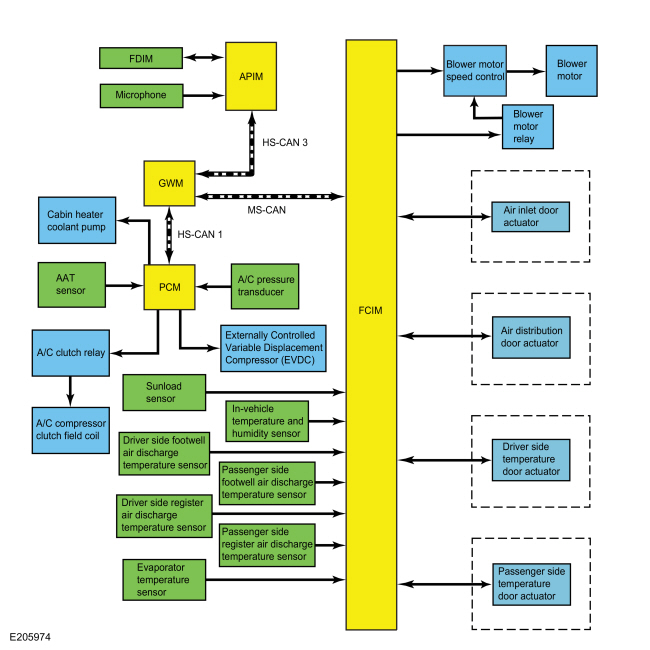
System Diagram
.jpg)
| Item | Description |
|---|---|
| 1 | FDIM |
| 2 | Microphone |
| 3 | APIM |
| 4 | GWM |
| 5 | Ambient Air Temperature (AAT) sensor |
| 6 | PCM |
| 7 | A/C pressure transducer |
| 8 | A/C clutch relay |
| 9 | A/C compressor clutch field coil |
| 10 | Externally Controlled Variable Displacement Compressor (EVDC) |
| 11 | Sunload sensor |
| 12 | In-vehicle temperature and humidity sensor |
| 13 | Driver side footwell air discharge temperature sensor |
| 14 | Passenger side footwell air discharge temperature sensor |
| 15 | Driver side register air discharge temperature sensor |
| 16 | Passenger side register air discharge temperature sensor |
| 17 | Evaporator temperature sensor |
| 18 | FCIM |
| 19 | Blower motor speed control |
| 20 | Blower motor |
| 21 | Air inlet door actuator |
| 22 | Air distribution door actuator |
| 23 | Driver side temperature door actuator |
| 24 | Passenger side temperature door actuator |
| 25 | Cabin heater coolant pump |
| 26 | Blower motor relay |
Network Message Chart
Module Network Input Messages APIM
| Broadcast Message | Originating Module | Message Purpose |
|---|---|---|
| Climate control button status | FCIM | This message contains the climate control button status. |
Module Network Input Messages FCIM
| Broadcast Message | Originating Module | Message Purpose |
|---|---|---|
| Ambient air temperature | PCM | This message contains raw value from the ambient air temperature sensor. |
| Climate control requests | APIM | This message contains both the climate control system voice commands as well as all climate control system touch screen inputs. |
| A/C clutch status | PCM | This message contains the status of the A/C compressor clutch. |
Module Network Input Messages PCM
| Broadcast Message | Originating Module | Message Purpose |
|---|---|---|
| HVAC A/C request | FCIM | This message requests the A/C compressor to be engaged. |
| Evaporator temperature | FCIM | This message contains the evaporator temperature. The PCM uses the evaporator temperature to determine the A/C compressor output. |
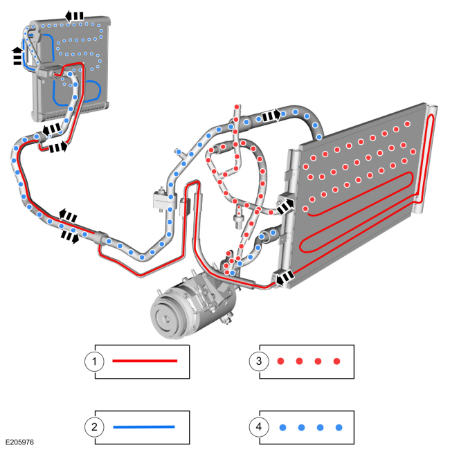
The Refrigerant Cycle
For information regarding basic HVAC system refrigerant operation, refer to the current Ford Web Based Technical Training courses. The following diagram shows the refrigerant system state in each component.
The following are characteristics of the DATC system:
- The PCM controls the A/C clutch relay.
- The evaporator temperature sensor monitors the temperature of the air that has passed through the evaporator core and sends a signal to the PCM. If the temperature of the evaporator core discharge air is low enough to cause the condensed water vapor to freeze, the PCM disengages the A/C clutch relay.
- The line pressure is monitored so that A/C compressor operation is interrupted if the system pressure becomes too high or too low.
- The A/C compressor relief valve opens and vents refrigerant to relieve unusually high system pressure.
A/C Flow and State
| Item | Description |
|---|---|
| 1 | High pressure liquid |
| 2 | Low pressure liquid |
| 3 | High pressure vapor |
| 4 | Low pressure vapor |
Control System Logic
The climate control system controls are in one or more locations depending on vehicle option content:
- FCIM (Dual Automatic Temperature Control (DATC) system)
- FDIM (part of APIM)
When the FDIM touchscreen or voice commands are used and A/C is selected, the APIM sends the request message over the HS-CAN3 to the GWM. The GWM relays the request to the FCIM over the MS-CAN, and the GWM sends the request to the PCM over the HS-CAN1. The PCM controls the A/C clutch relay.
When the customer directly inputs an A/C request into the FCIM, the module sends the request to the GWM over the MS-CAN, and the GWM sends the request to the PCM over the HS-CAN1. The PCM controls the A/C clutch relay.
Controls and Compressor Operation
When an A/C request is received by the PCM, the PCM engages the A/C clutch relay when all of the following conditions are met:
- The PCM does not detect excessively high or low refrigerant pressure from the A/C pressure transducer.
- The PCM does not detect an ambient air temperature below approximately 2°C (35.6°F).
- The PCM does not detect temperatures from the Mass Airflow/Intake Air Temperature sensor that does not correlate with other temperature sensor readings at ignition ON. (Most Mass Airflow (MAF) sensors have an integrated Intake Air Temperature (IAT) sensor).
- The PCM does not receive a message from the FCIM detecting an evaporator temperature below approximately 2°C (35.6°F).
Compressor control and the evaporator temperature are a function of many parameters, not a straight on off to avoid freezing the evaporator. The PCM monitors multiple temperature sensors correlation (AAT, CHT, ECT IAT, MAF (as equipped)). The PCM runs this logic after an engine off and a calibrated soak period, typically 6 to 8 hours. This soak period allows the Ambient Air Temperature (AAT) sensor and the other temperature sensors to stabilize and not differ by greater than a calibrated value, typically 18ºC (32.4ºF). If a sensor input is found to be reporting a temperature imbalance the PCM does not allow the A/C clutch to engage. For more information on PCM sensors, Refer to Powertrain Control/Emissions Diagnosis (PC/ED) manual.
The PCM monitors the discharge pressure measured by the A/C pressure transducer. The PCM interrupts A/C compressor operation in the event the A/C pressure transducer indicates high system discharge pressures. It is also used to sense low charge conditions. If the pressure is below a predetermined value for a given ambient temperature, the PCM does not allow the A/C clutch to engage.
The FCIM adjusts the air inlet door depending on the humidity measured by the in-vehicle temperature and humidity sensor. If the vehicle cabin becomes too humid and recirculated air is selected, the FCIM adjusts the air inlet door to allow more fresh air. When the humidity level drops, it may adjust back to partial recirculated air. The FCIM also adjusts the system based on in-vehicle temperature.
The sunload sensor supplies information to the FCIM indicating the intensity of the sun on the vehicle. The FCIM adjusts the system based on the intensity.
Heating and Ventilation
The heating and ventilation system:
- controls the temperature of the air inside the vehicle.
- reduces the relative humidity of the air inside the vehicle (during A/C compressor operation).
- delivers heated or cooled air to maintain the vehicle interior temperature and comfort level.
The heating and ventilation system uses a reheat method to provide conditioned air to the passenger compartment. Temperature blending is controlled by the temperature door(s), which regulate the amount of air that flows through and around the heater core, where it is then mixed and distributed. All airflow from the blower motor passes through the A/C evaporator core.
Vehicles equipped with Auto Start-Stop have a cabin heater coolant pump.
Air Handling
There are 4 door actuators that control the air flow into the passenger compartment:
- Air distribution
- Air inlet
- Driver side temperature
- Passenger side temperature
All of the door actuators contain a reversible electric motor and a potentiometer. The potentiometer circuit consists of a 5-volt reference signal connected to one end of a variable resistor, and a signal ground connected to the other. A signal circuit is connected to a contact wiper, which is driven along the variable resistor by the actuator shaft. The signal to the FCIM from the contact wiper indicates the position of the actuator door. The FCIM powers the actuator motors to move the doors to the desired positions. The desired door positions are calculated by the FCIM based on the set temperature, in-vehicle temperature, ambient air temperature and sunload.
When an airflow mode, desired driver or passenger temperature, fresh air, or recirculation mode is selected, the FCIM moves the actuator motor in the desired direction.
The FCIM sends a PWM signal to the blower motor speed control to regulate the blower speed as necessary. The blower motor speed control provides variable ground feed for the blower motor based on the input from the FCIM. A delay function provides a gradual increase or decrease in blower motor speed under all conditions.
AUTO
When AUTO is selected:
- the HVAC system operates in a manner to achieve and maintain the temperature set by the operator.
- the driver and passenger side temperature doors are automatically controlled by the FCIM based on the temperature setting.
- the A/C compressor is automatically controlled by the PCM from information sent by the FCIM, based on the temperature setting. The A/C compressor does not operate if the outside temperature is below approximately 2°C (35.6°F).
- the blower motor speed is automatically controlled through the blower motor speed control that receives a PWM signal from the FCIM based on the temperature setting, but can be manually overridden.
- the FCIM controls the air inlet door to recirculate, partially recirculate or open to the fresh air position depending on the in-car temperature and humidity sensor inputs.
OFF
When OFF is selected:
- the air inlet door closes, preventing outside air and allowing only recirculated air.
- the blower motor is off.
MAX A/C
When MAX A/C is selected:
- the air inlet door closes, preventing outside air and allowing only recirculated air.
- the recirculated air indicator is illuminated (recirculated air forced on).
- the footwell vent doors and defrost vent/register doors operate in combination to direct airflow to the instrument panel registers.
- the temperature doors move to the full cool position. Air temperature can be manually overridden.
- the A/C button is illuminated.
- the A/C compressor operates if the outside temperature is above approximately 2°C (35.6°F).
- the blower motor is commanded to the highest speed. The blower motor speed is adjustable.
PANEL
When PANEL mode is selected:
- the recirculated air request button is enabled. If the recirculated air request button is selected (indicator on), the air inlet door closes, preventing outside air from entering the passenger compartment. If the recirculated air request button is not selected (indicator off), the air inlet door opens, allowing only outside air into the passenger compartment.
- the footwell vent doors and defrost vent/register doors operate in combination to direct airflow to the instrument panel registers.
- blended air temperature is available. Only when A/C compressor operation has been selected by pressing the A/C button (indicator on) can the airflow temperature be cooled below the outside air temperature.
- the blower motor is on and the speed is adjustable.
PANEL/FLOOR
When PANEL/FLOOR mode is selected:
- the recirculated air request button is enabled. If the recirculated air request button is selected (indicator on), the air inlet door closes, preventing outside air from entering the passenger compartment. If the recirculated air request button is not selected (indicator off), the air inlet door opens, allowing only outside air into the passenger compartment.
- the air distribution doors operate in combination to direct airflow to the floor duct and the instrument panel registers. A small amount of airflow from the side window demisters and defrost duct is present.
- blended air temperature is available. Only when A/C compressor operation has been selected by pressing the A/C button (indicator on) can the airflow temperature be cooled below the outside air temperature.
- the blower motor is on and the speed is adjustable.
FLOOR
When FLOOR mode is selected:
- the recirculated air request button is enabled. If the recirculated air request button is selected (indicator on), the air inlet door closes, preventing outside air from entering the passenger compartment. If the recirculated air request button is not selected (indicator off), the air inlet door opens, allowing only outside air into the passenger compartment.
- the air distribution doors operate in combination to direct airflow to the floor duct. A small amount of airflow from the defroster duct and side window demisters is present.
- blended air temperature is available. Only when A/C compressor operation has been selected by pressing the A/C button (indicator on) can the airflow temperature be cooled below the outside air temperature.
- the blower motor is on and the speed is adjustable.
FLOOR/DEFROST
When FLOOR/DEFROST mode is selected:
- the recirculated air request button is enabled. If the recirculated air request button is selected (indicator on), the air inlet door closes, preventing outside air from entering the passenger compartment. If the recirculated air request button is not selected (indicator off), the air inlet door opens, allowing only outside air into the passenger compartment.
- the air distribution doors operate in combination to direct airflow to the floor duct, the defroster duct and the side window demisters.
- blended air temperature is available. Only when A/C compressor operation has been selected by pressing the A/C button (indicator on) can the airflow temperature be cooled below the outside air temperature.
- the blower motor is on and the speed is adjustable.
MAX DEFROST
When MAX DEFROST mode is selected:
- The recirculated air request button is disabled. The air inlet door opens, allowing only outside air into the passenger compartment.
- The air distribution doors operate in combination to direct airflow to the defroster duct and side window demisters. A small amount of airflow from the floor duct is present.
- The A/C is turned on in defrost mode. The A/C compressor operates as long as the outside temperature is above approximately 2°C (35.6°F).
- The temperature is set to the highest setting and is not adjustable.
- The fan is set to the highest speed and is not adjustable.
- MAX DEFROST can be exited by pressing the AUTO button.
MyTemp
The MyTemp feature can be used to store and recall a preset driver's temperature. This feature is provided so this temperature can be quickly adjusted to a frequently used setting with a single button press. For additional information about MyTemp, refer to the Owner's Literature.
Remote Start - Message Center Set To Auto
Remote start is an optional feature available on this vehicle. In addition to being able to start the vehicle remotely, the remote start feature also utilizes other vehicle systems to increase the level of comfort to the vehicle occupants upon entering the vehicle. Additional information on the remote start feature and the other vehicle systems, refer to Owner's Literature.
Set the climate control to operate in Auto mode through the information display setting: Remote Start > Climate Control > Heater–A/C > Auto, refer to the Owner's Literature for more information.
When the factory remote start feature is used, the Dual Automatic Temperature Control (DATC) system automatically sets certain parameters in an attempt to achieve a comfortable cabin temperature. These parameters are set based on outside air temperature. During remote start, the outside air temperature is continually evaluated and HVAC system behavior can change if the outside air changes between cold, moderate and warm temperatures.
For cold ambient air temperatures as determined by the FCIM AUTO mode to request heat:
- the airflow mode is set to AUTO if Front Defrost is set to Off in the message center. (if the FCIM requests FOOTWELL in AUTO mode, FOOTWELL/DEFROST will be used in remote start mode).
- the airflow mode is set to DEFROST if Front Defrost is set to Auto in the message center.
- the temperature is set to 22 C (71.6 F).
- the blower speed is set to AUTO.
- the air inlet mode is set to AUTO.
- A/C is set to AUTO.
For moderate and warm ambient air temperatures as determined by the FCIM AUTO mode to request heat or cooling:
- the airflow mode is set to AUTO.
- the temperature is set to 22 C (71.6 F).
- the blower speed is set to AUTO.
- the air inlet mode is set to AUTO.
- A/C is set to AUTO.
Remote Start - Message Center Set To Last User Settings
Remote start is an optional feature available on this vehicle. In addition to being able to start the vehicle remotely, the remote start feature also utilizes other vehicle systems to increase the level of comfort to the vehicle occupants upon entering the vehicle. Additional information on the remote start feature and the other vehicle systems, refer to Owner's Literature.
Set the climate control to operate using the last climate control settings through the information display setting: Remote Start > Climate Control > Heater–A/C > Last Settings, refer to the Owner's Literature for more information.
When the factory remote start feature is used and the IPC message center is set to last user settings, the Dual Automatic Temperature Control (DATC) system automatically sets certain parameters in an attempt to achieve a comfortable cabin temperature. These parameters are set based on outside air temperature. During remote start, the outside air temperature is continually evaluated and HVAC system behavior can change if the outside air changes between cold, moderate and warm temperatures.
For cold ambient air temperatures as determined by the FCIM AUTO mode to request heat:
- the airflow mode is set to the last user setting if Front Defrost is set to Off in the message center.
- the airflow mode is set to DEFROST if Front Defrost is set to Auto in the message center.
- the temperature is set to the last user setting.
- the blower speed is set to the last user setting.
- the air inlet mode is set to the last user setting.
- A/C is set to the last user setting.
For moderate and warm ambient air temperatures as determined by the FCIM AUTO mode to request heat or cooling:
- the airflow mode is set to the last user setting.
- the temperature is set to the last user setting.
- the blower speed is set to the last user setting.
- the air inlet mode is set to the last user setting.
- A/C is set to the last user setting.
Component Description
FCIM - Dual Automatic Temperature Control (DATC)
The Dual Automatic Temperature Control (DATC) system uses the FCIM as the HVAC control module. The FCIM also controls the outputs for rear window defrost and climate controlled seats. For vehicles equipped with touchscreen audio, the Dual Automatic Temperature Control (DATC) system uses voice commands or the touchscreen to control the system. For details on the FCIM communication, refer to Control System Logic in this section.
The FCIM utilizes a Field-Effect Transistor (FET) protective circuit strategy for its actuator outputs. Output load (current level) is monitored for excessive current (typically short circuits) and is shut down (turns off the voltage or ground provided by the module) when a fault event is detected. A short circuit DTC is stored at the fault event and a cumulative counter is started.
When the demand for the output is no longer present, the module resets the Field-Effect Transistor (FET) circuit protection to allow the circuit to function. The next time the driver requests a circuit to activate that has been shut down by a previous short (Field-Effect Transistor (FET) protection) and the circuit is still shorted, the Field-Effect Transistor (FET) protection shuts off the circuit again and the cumulative counter advances.
When the excessive circuit load occurs often enough, the module shuts down the output until a repair procedure is carried out. The Field-Effect Transistor (FET) protected circuit has 3 predefined levels of short circuit tolerance based on the harmful effect of each circuit fault on the Field-Effect Transistor (FET) and the ability of the Field-Effect Transistor (FET) to withstand it. A module lifetime level of fault events is established based upon the durability of the Field-Effect Transistor (FET). If the total tolerance level is determined to be 600 fault events, the 3 predefined levels would be 200, 400 and 600 fault events.
When each tolerance level is reached, the short circuit DTC that was stored on the first failure cannot be cleared by a command to clear the Diagnostic Trouble Codes (DTCs). The module does not allow the DTC to be cleared or the circuit to be restored to normal operation until a successful self-test proves that the fault has been repaired. After the self-test has successfully completed (no on-demand Diagnostic Trouble Codes (DTCs) present), DTC U1000:00 and the associated DTC (the DTC related to the shorted circuit) automatically clears and the circuit function returns.
When each level is reached, the DTC associated with the short circuit sets along with DTC U1000:00. These Diagnostic Trouble Codes (DTCs) can be cleared using the module self-test, then the Clear DTC operation on the scan tool. The module never resets the fault event counter to zero and continues to advance the fault event counter as short circuit fault events occur.
If the number of short circuit fault events reach the third level, then Diagnostic Trouble Codes (DTCs) U1000:00 and U3000:49 set along with the associated short circuit DTC. DTC U3000:49 cannot be cleared and a new module must be installed after the repair.
For FCIM programming information,
Refer to: Module Configuration - System Operation and Component Description (418-01 Module Configuration, Description and Operation).
Cabin Heater Coolant Pump - vehicles equipped with Auto-Start-Stop
The cabin heater coolant pump is available on vehicles equipped with Auto-Start-Stop feature. The cabin heater coolant pump provides coolant to the heater core whenever the HVAC system requests heat and the vehicle is in Auto-Start-Stop mode. The cabin heater coolant pump provides coolant flow to the engine when the engine is shut down to provide additional cooling to the engine components. This pump varies in runtime. With the engine shutdown and the cabin heater coolant pump in normal operation there can be a noticeable humming sound. Refer to the Owner's Literature, Unique Driving Characteristics, for full Auto-Start-Stop enabling/disabling information.
The PCM sends a PWM signal to the cabin heater coolant pump based upon the:
- Auto-Start-Stop mode enabled
- HVAC system temperature control setting (requesting heat)
- Ambient air temperature
- Engine coolant temperature
- Engine Revolutions Per Minute (RPM)
- Vehicle speed
Ambient Air Temperature (AAT) Sensor
The Ambient Air Temperature (AAT) sensor contains a thermistor. The sensor varies its resistance with the temperature. As the temperature rises, the resistance falls. As the temperature falls, the resistance rises. The Ambient Air Temperature (AAT) sensor is hardwired to the PCM through separate input and return circuits. If the outside air temperature is below approximately 2°C (35.6°F), the PCM does not allow the A/C compressor clutch to engage.
The PCM sends raw ambient air temperature data to the HVAC module. The HVAC module filters the raw data, sends it to the APIM and the touchscreen displays the outside temperature.
After replacing an Ambient Air Temperature (AAT) sensor, the sensor data must be reset by either driving the vehicle at speeds consistently about 20 MPH for at least 5 minutes to update the filtered data or perform the multiple button press reset procedure to update to the current raw value.
The multiple button reset for the Ambient Air Temperature (AAT) sensor is as follows:
- On the HVAC panel controls, press the A/C and Recirc buttons simultaneously, then, release both.
- Within 2 seconds press the A/C button again.
Blower Motor
The blower motor pulls air from the air inlet and forces it into the heater core and evaporator core housing and the plenum chamber where it is mixed and distributed.
Blower Motor Speed Control
The blower motor speed control uses a PWM signal from the FCIM to determine the desired blower speed and varies the ground feed for the blower motor to control the speed.
Evaporator Core
The evaporator core is an aluminum tube and fin design heat exchanger located in the climate control housing. A mixture of liquid refrigerant and oil enters through the evaporator core inlet tube and exits out of the evaporator core through the evaporator core outlet tube as a vapor. During A/C compressor operation, airflow from the blower motor is cooled and dehumidified as it flows through the evaporator core fins.
Heater Core
The heater core consists of fins and tubes arranged to extract heat from the engine coolant and transfer it to air passing through the heater core.
Climate Control Housing
The climate control housing directs airflow from the blower motor through the evaporator core and heater core. All airflow from the blower motor passes through the evaporator core. The airflow is then directed through or around the heater core by the temperature door(s). After passing through the heater core, the airflow is distributed to the selected outlet by the airflow mode doors.
Air Distribution Door Actuator
The air distribution door actuator contains a reversible electric motor and a potentiometer. The potentiometer allows the FCIM to monitor the position of the airflow mode door.
Air Inlet Door Actuator
The air inlet door actuator contains a reversible electric motor and a potentiometer. The potentiometer allows the FCIM to monitor the position of the airflow mode door. The FCIM drives the actuator motor in the direction necessary to move the door to the position set by the recirculation button and the in-vehicle temperature and humidity sensor information.
Driver Side Temperature Door Actuator
The driver side temperature door actuator contains a reversible electric motor and potentiometer. The potentiometer allows the FCIM to monitor the position of the temperature door.
Passenger Side Temperature Door Actuator
The passenger side temperature door actuator contains a reversible electric motor and potentiometer. The potentiometer allows the FCIM to monitor the position of the temperature door.
A/C Pressure Transducer
The PCM monitors the discharge pressure measured by the A/C pressure transducer. As the refrigerant pressure changes, the resistance of the A/C pressure transducer changes. It is not necessary to recover the refrigerant before removing the A/C pressure transducer.
A 5-volt reference voltage is supplied to the A/C pressure transducer from the PCM. The A/C pressure transducer receives a ground from the PCM. The A/C pressure transducer then sends a voltage to the PCM to indicate the A/C refrigerant pressure.
In-Vehicle Temperature And Humidity Sensor
The in-vehicle temperature and humidity sensor contains a thermistor and a sensing element which separately measures the in-vehicle air temperature and the humidity, then sends those readings to the FCIM. The in-vehicle temperature and humidity sensor has an electric fan within the sensor that draws in-vehicle air across the two sensing elements. The FCIM may adjust the air inlet door based on the in-vehicle temperature and humidity sensor information to maintain the desired humidity of the passenger cabin air.
Sunload Sensor
The sunload sensor supplies information to the FCIM indicating the intensity of the sun on the vehicle. The FCIM compensates high sun load with higher blower and reduced discharge temperatures.
Evaporator Temperature Sensor
The evaporator temperature sensor contains a thermistor. The sensor varies its resistance with the temperature. As the temperature rises, the resistance falls. As the temperature falls, the resistance rises. The evaporator temperature sensor is an input to the FCIM and the information is relayed to the PCM over the CAN. If the temperature is below a predetermined value, the PCM does not allow the A/C compressor to operate.
Air Discharge Temperature Sensors
There are 4 air discharge temperature sensors in the Dual Automatic Temperature Control (DATC) system:
- Driver side register air discharge temperature sensor
- Driver side footwell air discharge temperature sensor
- Passenger side register air discharge temperature sensor
- Passenger side footwell air discharge temperature sensor
All 4 air discharge temperature sensors contain a thermistor and are inputs to the FCIM. The sensors vary their resistance with the temperature. As the temperature rises, the resistance falls. As the temperature falls, the resistance rises. The FCIM uses the sensor information to maintain the desired temperature of the passenger cabin air.
Internal Heat Exchanger (IHX)
The evaporator inlet and outlet manifold incorporates the Internal Heat Exchanger (IHX) and is serviced as an assembly. The Internal Heat Exchanger (IHX) combines a section of the A/C suction and liquid refrigerant lines into one component. It uses the cold vapor from the evaporator to cool the hot liquid from the condenser before it enters the Thermostatic Expansion Valve (TXV). After the Thermostatic Expansion Valve (TXV), more liquid refrigerant is available for absorbing heat in the evaporator. The result is an increase in cooling and operating efficiency of the HVAC system.
Externally Controlled Variable Displacement A/C Compressor
NOTE: Proper Air Conditioning (A/C) system diagnosis on a vehicle's compressor is dependent on correct refrigerant system charge and tested in ambient temperatures above 21.1°C (70°F).
The externally controlled variable displacement compressor has:
- a non-serviceable shaft seal.
- a non-serviceable pressure relief valve installed in the rear of the compressor to protect the refrigerant system against excessively high refrigerant pressures.
- Refer to Specifications in Group 412 for the appropriate refrigerant and refrigerant oil. This oil contains special additives required for the A/C compressor. The oil may have some slightly dark-colored streaks while maintaining normal oil viscosity. This is normal for this A/C compressor because of break-in wear that can discolor the oil.
Variable displacement compressors have a swash plate that rotates to reciprocate pistons, which compresses refrigerant. Variable displacement compressors change the swash plate angle to change the refrigerant displacement. The externally controlled variable displacement compressor changes the swash plate angle in response to an electrical signal from the PCM. The externally controlled variable displacement compressor manages displacement by controlling refrigerant differential pressure before and after a throttle at the discharge side; achieving precise cooling capability control in response to cabin environment and driving conditions.
The PCM sends a PWM signal to the solenoid in the compressor to control the compressor displacement based upon the:
- Ambient air temperature
- Evaporator temperature
- Engine RPM
- Vehicle speed
- A/C high side pressure
- Temperature and mode settings of the climate control head
- Intake air temperature
Thermostatic Expansion Valve (TXV)
The Thermostatic Expansion Valve (TXV) is located at the evaporator core inlet and outlet tubes at the center rear of the engine compartment. The TXV provides a restriction to the refrigerant flow and separates the low-pressure and high-pressure sides of the refrigerant system. Refrigerant entering and exiting the evaporator core passes through the TXV through 2 separate flow paths. An internal temperature sensing bulb senses the temperature of the refrigerant flowing out of the evaporator core and adjusts an internal pin-type valve to meter the refrigerant flow into the evaporator core. The internal pin-type valve decreases the amount of refrigerant entering the evaporator core at lower temperatures and increases the amount of refrigerant entering the evaporator core at higher temperatures.
Condenser
The A/C condenser is an aluminum fin-and-tube design heat exchanger. It cools compressed refrigerant gas by allowing air to pass over fins and tubes to extract heat, and condenses gas to liquid refrigerant as it is cooled. The receiver drier is integral to the A/C condenser.
Integrated Receiver Drier
The integrated receiver drier stores high-pressure liquid and the desiccant bag mounted inside the receiver drier removes any retained moisture from the refrigerant.
The receiver drier element is incorporated onto the LH side of the A/C condenser. The receiver drier element can be separately removed and installed with the A/C condenser in the vehicle.
Service Gauge Port Valves
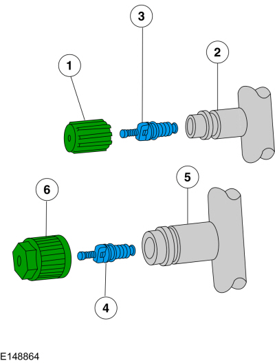
| Item | Description | Torque |
| 1 | Low-pressure service gauge port valve cap | 0.8 Nm (7 lb-in) |
| 2 | Low-pressure service gauge port valve | — |
| 3 | Low-pressure Schrader-type valve | 1.8 Nm (16 lb-in) |
| 4 | High-pressure Schrader-type valve | 2.5 Nm (22 lb-in) |
| 5 | High-pressure service gauge port valve | — |
| 6 | High-pressure service gauge port valve cap | 0.8 Nm (7 lb-in) |
The service gauge port fitting is an integral part of the refrigerant line or component.
- Prior to leak testing, blow air over service gauge port valves to insure an accurate test.
- Special couplings are required for both the high-side and low-side service gauge ports.
- A very small amount of leakage around the Schrader-type valve with the service gauge port valve cap removed is considered normal. Install a new Schrader-type valve core if the seal leaks excessively.
- The A/C service gauge port valve caps are used as primary seals in the refrigerant system to prevent leakage through the Schrader-type valves from reaching the atmosphere. Always install and tighten the A/C service gauge port valve caps to the correct torque after they are removed.
-
Follow the procedure and the notes for electronic leak testing.
Refer to: Electronic Leak Detection - Vehicles With: R1234YF Refrigerant (412-00 Climate Control System - General Information, General Procedures).
Refrigerant System Dye
A
fluorescent refrigerant system dye wafer is added to the receiver drier
desiccant bag at the factory to assist in refrigerant system leak
diagnosis. This fluorescent dye wafer dissolves after about 30 minutes
of continuous A/C operation. It is
not necessary to add additional dye to the refrigerant system before
diagnosing leaks, even if a significant amount of refrigerant has been
removed from the system.
Refer to: Fluorescent Dye Leak Detection - Vehicles With: R1234YF Refrigerant (412-00 Climate Control System - General Information, General Procedures).
Replacement desiccant bags, either separately or part of the receiver drier assembly, are equipped with a new fluorescent dye wafer. It is not necessary to add additional dye to the refrigerant system before diagnosing leaks. If the system has been out of refrigerant through the winter the dye at the leak point may have oxidized and may not fluoresce. If this happens, recharge and operate the A/C system to circulate the oil and allow any residual dye to show up at the leak point. It is important to understand that dye adheres to the oil not the refrigerant; the refrigerant carries the oil out of the leak point.
NOTE: Check for leaks using a Rotunda-approved UV lamp and dye enhancing glasses.
 Climate Control System - Vehicles With: Dual Automatic Temperature Control (DATC) - Overview. Description and Operation
Overview
The
Dual Automatic Temperature Control (DATC) system maintains the selected
vehicle interior temperature by heating and/or cooling the air
depending on the HVAC control panel selection...
 Climate Control System - Vehicles With: Electronic Manual Temperature Control (EMTC) - Component Location. Description and Operation
Item
Description
1
Heating, Ventilation, and Air Conditioning (HVAC) Module
2
In-vehicle temperature & humidity Sensor
3
Driver Side Footwell Air Discharge Temperature Sensor
Item
Description
1
Heater Core
2
Evaporator Temperature Sensor
3
Air Distribution Door Actuator
4
Air Distribution Door A..
Other information:
Ford Fusion 2013–2020 Service Manual: Handles, Locks, Latches and Entry Systems - System Operation and Component Description. Description and Operation
System Operation System Diagram Item Description 1 Exterior Door Handles 2 BCM 3 Luggage Compartment Lid Release Switches 4 DDM 5 RDM 6 PDM 7 RDM 8 Lock Actuator 9 Lock/Unlock Feedback 10 Left Rear Door Latch 11 Lock Actuator 12 Lock/Unlock Feedback 13 Right Front Door Latch 14 Passive Key 1..
Ford Fusion 2013–2020 Service Manual: Crankcase Vent Oil Separator. Removal and Installation
Special Tool(s) / General Equipment Hose Clamp Remover/Installer Removal NOTE: Removal steps in this procedure may contain installation details. Remove the intake manifold. Refer to: Intake Manifold (303-01A Engine - 1.5L EcoBoost (118kW/160PS) – I4, Removal and Installation). Remove the starter motor. Refer to: Starter Motor (303-06A Starting System - 1.5L E..
Categories
- Manuals Home
- 2nd Generation Ford Fusion Owners Manual
- 2nd Generation Ford Fusion Service Manual
- Load Carrying
- Body Control Module (BCM). Removal and Installation
- Starter Motor. Removal and Installation
- New on site
- Most important about car
Cross Traffic Alert System Sensors
The sensors are behind the rear bumper on both sides of your vehicle.