
Ford Fusion: Auxiliary Power Points
Ford Fusion 2013–2020 Owners Manual / Auxiliary Power Points
 Garage Door Opener
HomeLink Wireless Control System
WARNING: Do not use the system
with any garage door opener that does
not have the safety stop and reverse
feature as required by U...
 12 Volt DC Power Point
WARNING: Do not plug optional
electrical accessories into the cigar
lighter socket. Incorrect use of the cigar
lighter can cause damage not covered
by the vehicle warranty, and can result
in fire or serious injury...
Other information:
Ford Fusion 2013–2020 Service Manual: Fuel Pressure Sensor. Removal and Installation
Removal NOTE: Removal steps in this procedure may contain installation details. WARNING: Before beginning any service procedure in this section, refer to Safety Warnings in section 100-00 General Information. Failure to follow this instruction may result in serious personal injury...
Ford Fusion 2013–2020 Owners Manual: Brake Fluid Check
WARNING: Do not use any fluid other than the recommended brake fluid as this will reduce brake efficiency. Use of incorrect fluid could result in the loss of vehicle control, serious personal injury or death. WARNING: Only use brake fluid from a sealed container...
Categories
- Manuals Home
- 2nd Generation Ford Fusion Owners Manual
- 2nd Generation Ford Fusion Service Manual
- Engine Cooling System Draining, Vacuum Filling and Bleeding. General Procedures
- Powertrain
- Engine
- New on site
- Most important about car
Cross Traffic Alert System Sensors
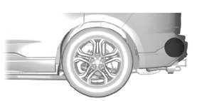
The sensors are behind the rear bumper on both sides of your vehicle.

Copyright © 2026 www.fofusion2.com