Ford Fusion: Anti-Lock Brake System (ABS) and Stability Control / Anti-Lock Brake System (ABS) and Stability Control - System Operation and Component Description. Description and Operation
System Operation
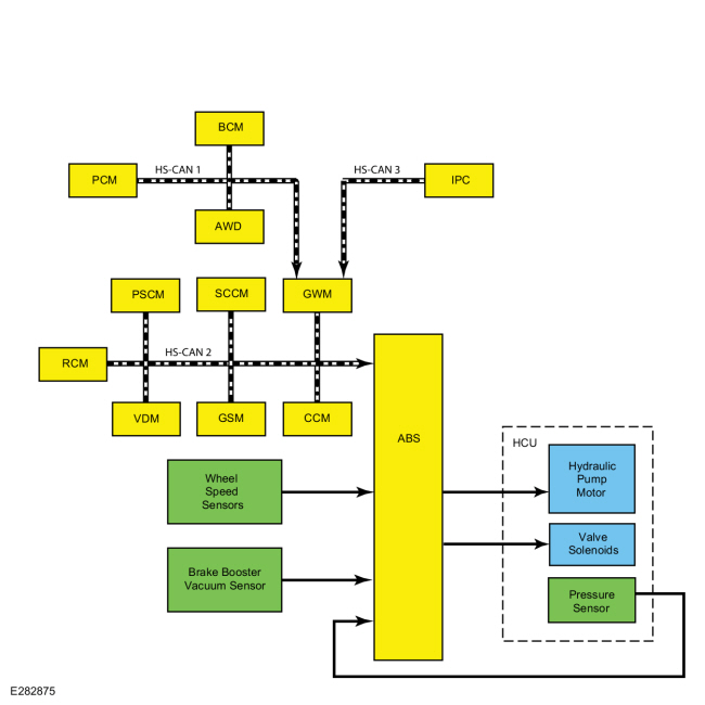
System Diagram
.jpg)
| Item | Description |
|---|---|
| 1 | Hydraulic Pressure Sensor |
| 2 | HCU |
| 3 | ABS module |
| 4 | Hydraulic Pump Motor |
| 5 | Brake Booster Vacuum Sensor |
| 6 | Wheel Speed Sensors |
| 7 | Hydraulic Valve Solenoids |
| 8 | GWM |
| 9 | RCM |
| 10 | PSCM |
| 11 | AWD module |
| 12 | BCM |
| 13 | CCM |
| 14 | PCM |
| 15 | VDM |
| 16 | GSM |
| 17 | SCCM |
| 18 | IPC |
Network Message Chart
Module Network Input Messages - ABS Module
| Broadcast Message | Originating Module | Message Purpose |
|---|---|---|
| Accelerator pedal position | PCM | This message is sent to the GWM and then to the ABS module. The ABS module uses accelerator pedal position information for correct operation of the ABS, traction control, ESC and the automatic release feature of the electronic parking brake system. |
| Adaptive cruise control braking deceleration | CCM | This message is used to request vehicle deceleration by the ABS module to maintain the distance gap set by the driver for the adaptive cruise control system. |
| Adaptive cruise control brake torque request | CCM | This message informs the ABS module of the amount of braking required to maintain the distance gap set by the driver for the adaptive cruise control system. |
| Adaptive cruise control precharge request | CCM | This message is used to request precharging of the hydraulic brake system in preparation of a severe braking event. |
| Ambient air temperature | PCM | This message is sent to the GWM and then to the ABS module. This message informs the ABS module of the current ambient air temperature. The ABS module uses this information for calculations in determining the operational status of the various stability control systems and features. |
| Auto hold switch | FCIM | This message is sent to the GWM and then to the ABS module. This message informs the ABS module of the current auto hold switch status; pressed, not pressed, faulty or not used. |
| AWD locking status | AWD module | This message is sent to the GWM and then to the ABS module. The ABS module uses AWD information for correct operation of the ABS and stability control systems. |
| AWD torque status | AWD module | This message is sent to the GWM and then to the ABS module. The ABS module uses AWD torque information to aid in stability control system operation. |
| Battery voltage | BCM | This message is sent to the GWM and then to the ABS module. This message informs the ABS module of the current battery voltage. The ABS module uses this information to monitor fault setting conditions. |
| Brake on/off switch | PCM | This message is sent to the GWM and then to the ABS module. This message informs the ABS module the driver has pressed the brake pedal. This message is also used by the ABS module to check the brake pressure sensor located inside the HCU. |
| Brake pedal applied | PCM | This message is sent to the GWM and then to the ABS module. This message informs the ABS module the driver has pressed the brake pedal. This message is also used by the ABS module to check the brake pressure sensor located inside the HCU. |
| Collision mitigation by braking precharge request | CCM | This message is used to request precharging of the hydraulic brake system in preparation of a severe braking event. |
| Cruise control override | PCM | This message is sent to the GWM and then to the ABS module. This message informs the ABS module the PCM has overridden the cruise control request. When the ABS module receives this message, any other cruise control messages are ignored until the "not overridden" message is received. |
| Cruise control status | PCM | This message is sent to the GWM and then to the ABS module. This message informs the ABS module the current cruise control system status; off, denied, standby_denied, standby, active_que_assist or active. |
| Door ajar status | BCM | This message is sent to the GWM and then to the ABS module. This message informs the ABS module of the current door ajar status. There is a separate message for each door, the hood and the trunk. The ABS module resets the parameters used for the ESC function when a door is opened. The driver door message is also used for the auto hold feature and the electronic parking brake automatic release feature. |
| Driven wheel torque | PCM | This message is sent to the GWM and then to the ABS module. This message informs the ABS module of the current torque available at the driven wheels. |
| Driver safety belt buckle | RCM | This message informs the ABS module of the current driver safety belt buckle status; buckled or unbuckled. The ABS module uses this information for the auto hold feature. |
| EPAS information | PSCM | Several steering angle messages are sent to the ABS module from the PSCM. These messages include steering angle sensor status, steering wheel angle and steering wheel rotation count. The ABS module uses the steering angle sensor data for ESC system operation. |
| EPAS steering request | PSCM | This message informs the ABS module an active park event is taking place and the EPAS system is busy steering the vehicle. |
| Engine RPM | PCM | This message is sent to the GWM and then to the ABS module. This message provides the ABS module with the current engine RPM. The ABS module uses this information for the auto hold feature, hill start assist feature, traction control and ESC. |
| Engine status | PCM | This message is sent to the GWM and then to the ABS module. This message informs the ABS module of the current status of the engine system; off, on or engine auto stopped. |
| Gear lever position | PCM | This message is sent to the GWM and then to the ABS module. This message informs the ABS module of the current transmission gear lever position, this is used for the hill start assist system and the ESC system. The hill start assist system operates in forward and reverse gears. The ESC system does not operate when the transmission is in REVERSE. The message is also used for the electronic parking brake automatic release feature. |
| Hill start assist request | IPC | This message is sent to the GWM and then to the ABS module. This message informs the ABS module of the current, driver selected mode for the hill start assist system; off, auto or manual. |
| Ignition status | BCM | This message is sent to the GWM and then to the ABS module. This message informs the ABS module of the current ignition status; off, accessory, run, start, unknown or invalid. |
| Ignition key type | BCM | This message is sent to the GWM and then to the ABS module. This message informs the ABS module of the current ignition key type; a standard ignition key or a MyKey® ignition key. |
| Lateral acceleration data | RCM | This message provides the ABS module with the current vehicle lateral acceleration information and whether or not the information is valid. |
| Longitudinal acceleration data | RCM | This message provides the ABS module with the current vehicle longitudinal acceleration information and whether or not the information is valid. |
| Powertrain torque status | PCM | This message is sent to the GWM and then to the ABS module. This message informs the ABS module of the current ability of the powertrain to provide torque for stability control system operation; power pack off_torque not available, power pack on_torque not available, start in progress_torque not available and power pack on_torque available. |
| Odometer value | IPC | This message is sent to the GWM and then to the ABS module. This message informs the ABS module of the current odometer mileage. |
| PATS start request target data | PCM | This message is sent to the GWM and then to the ABS module. This message supplies the ABS module with the PCM challenge ID. If the ABS module ID response is correct, the engine is allowed to start. |
| Reverse gear selected | PCM | This message is sent to the GWM and then to the ABS module. This message informs the ABS module the driver has requested REVERSE gear and the current status of REVERSE gear; active, inactive or faulted. This message is used for operation of the hill start assist feature and the ESC feature. The hill start assist feature operates in forward and reverse gears but the ESC feature does not operate when the transmission is in REVERSE. |
| RCM serial number | RCM | The ABS module stores the RCM serial number and verifies the serial number when the vehicle is started or the ignition is set to RUN or ACC. Over time, the ABS module learns the offset of the sensors inside the RCM. When a new serial number is found and the IVD Initialization procedure is carried out using a diagnostic scan tool, the ABS module resets the offset number learned for ESC. |
| Steering angle sensor data | PSCM | Several steering angle messages are sent to the ABS module from the PSCM. These messages include steering angle sensor status, steering wheel angle and steering wheel rotation count. The ABS module uses the steering angle sensor data for ESC system operation. |
| Traction control mode request | IPC | This message is sent to the GWM and then to the ABS module. This message informs the ABS module of the current driver selected traction control mode made through the message center. |
| Transmission in reverse | PCM | This message is sent to the GWM and then to the ABS module. This message informs the ABS module when the transmission is in REVERSE, this is used for the hill start assist system and the ESC system. The hill start assist system operates in forward and reverse gears. The ESC system does not operate when the transmission is in REVERSE. |
| Vehicle configuration data | BCM | This message is sent to the GWM and then to the ABS module. This message provides the ABS module with the current optional and configured items such as tire size, axle ratio, manual or automatic transaxle, keyless entry and VIN. |
| Vehicle dynamic data display | VDM | Used to inform the ABS module of the current vehicle suspension mode; comfort, normal, sport, faulty, service required, temporarily off, or mode change unavailable. This message is used by the ABS module for traction control and ESC performance. |
| Yaw rate data | RCM | This message provides the ABS module with the current vehicle yaw rate information and whether or not the information is valid. |
Anti-Lock Brake System (ABS)
The ABS module continuously monitors brake pedal input, longitudinal vehicle motion and the rotational speed of each wheel. The ABS module receives the brake pedal input from the PCM and the longitudinal acceleration sensor information from the RCM. Both the PCM and the RCM send the information to the GWM over the HS-CAN1. The GWM then relays the information to the ABS module over the HS-CAN2. Wheel speed information is received by the ABS module using 4 wheel speed sensors. When the ABS module detects an impending wheel lock during a braking event, the ABS module modulates brake pressure to the appropriate brake caliper(s) by opening and closing the appropriate solenoid valves inside the HCU while the hydraulic pump motor is activated. Once the affected wheel(s) return to the desired speed, the ABS module returns the solenoid valves in the HCU to their normal position.
When the ABS module is initialized (ignition ON), it carries out a preliminary electrical check of the system sensors and activates the hydraulic pump motor for approximately one-half second. During this time, a buzzing or humming noise may be heard and a vibration may be felt in the brake pedal and is a normal condition. During the module initialized self-test, the pump motor check is carried out at approximately 10 km/h (6.2 mph). Any malfunction detected in the system causes the module to set a DTC, disable the ABS function and send a message over the HS-CAN2 to the GWM. The GWM then sends a message to the IPC over the HS-CAN3 to illuminate the ABS warning indicator. The base hydraulic power assist braking system functions normally.
Electronic Brake Force Distribution (EBD)
On initial application of the brake pedal, full pressure is applied to the rear brakes. The ABS module then uses wheel speed sensor inputs to evaluate rear wheel slip. Once the rear wheel slip exceeds a predetermined threshold, the ABS module commands the HCU to close the appropriate isolation valves to hold the rear brake pressure constant while allowing the front brake pressure to build. This creates a balanced braking condition between the front and rear wheels. If the rear wheel slip continues and exceeds a second predetermined threshold, the ABS module commands the HCU to open the dump valves to decrease the rear brake pressure and allow the rear wheels to recover. A slight bump sensation may be felt in the brake pedal when EBD is active.
If the ABS is disabled due to a DTC being present in the ABS module, EBD continues to function unless the DTC is for wheel speed sensors or the HCU. When EBD is disabled, the ABS warning indicator, the red brake warning indicator and stability/traction control indicator (sliding car icon) illuminate.
Supplemental Braking Assist
The ABS module uses the HCU and hydraulic pump motor to help bring the vehicle to a safe, controlled stop in the event of severe vacuum loss in the brake booster. The ABS module continually monitors the vacuum in the brake booster through the use of a vacuum sensor. When the vacuum sensor indicates vacuum is below a predetermined level, a DTC is set in the ABS module. The ABS module sends a message to the GWM over the HS-CAN2 to illuminate the red brake warning indicator, the GWM relays this message to the IPC over the HS-CAN3. If a low vacuum condition occurs during a braking event or if the driver attempts to stop the vehicle with a low vacuum condition in the brake booster, the ABS module activates the hydraulic pump motor in the HCU to assist with vehicle braking.
On vehicles equipped with adaptive cruise control, the CCM monitors the area forward of the vehicle. When an object enters this area and closes the distance gap set by the driver, the CCM sends either an adaptive cruise control deceleration request or a collision avoidance deceleration request to the ABS module over the HS-CAN2. When the deceleration request message is received, the ABS module activates the hydraulic pump motor and solenoid valves in the HCU to slow the vehicle down to maintain the distance gap set by the driver. Once the distance gap set by the driver is achieved, the CCM stops sending the deceleration request message and the ABS module deactivates the hydraulic pump motor and solenoid valves in the HCU. If the CCM determines the amount of braking provided by the ABS module is insufficient, the CCM sends a forward collision avoidance braking request message to the ABS module and warns the driver, both audibly and visually, through the use of the HUD. After receiving the braking request message, the ABS module waits for brake pedal input and then applies maximum braking assist using the hydraulic pump motor and the HCU.
Refer to: Cruise Control - System Operation and Component Description (419-03A Cruise Control, Description and Operation).
Refer to: Collision Warning and Collision Avoidance System - System Operation and Component Description (419-03B Collision Warning and Collision Avoidance System, Description and Operation).
Traction Control
The ABS module continuously monitors and compares the rotational speed of the drive wheels in relation to the non-driven wheels. When the drive wheels begin to spin faster than the non-driven wheels, the ABS module modulates brake pressure to the appropriate brake caliper(s) by opening and closing the appropriate solenoid valves inside the HCU while the hydraulic pump motor is activated. At the same time, the ABS module calculates how much engine torque reduction is required to eliminate the wheel slip and sends this torque reduction message along with a traction event message to the GWM over the HS-CAN2. The GWM sends the engine torque reduction message to the PCM over the HS-CAN1 and the traction event message to the IPC over the HS-CAN3. When the PCM receives the torque reduction message, it adjusts engine timing and decreases fuel injector pulses to reduce the engine torque to the requested level. When the IPC receives the traction event message it flashes the stability-traction control indicator (sliding car icon). Once the driven wheel speed returns to the desired speed, the ABS module returns the solenoid valves in the HCU to their normal position, deactivates the hydraulic pump motor and stops sending the traction event and torque reduction messages. The PCM returns engine timing and fuel injectors to normal operation and the IPC extinguishes the stability-traction control indicator (sliding car icon). After the vehicle speed exceeds 100 km/h (62.1 mph), traction control is accomplished only through the PCM torque control.
Traction control can be disabled through the menu in the message center, refer to the Owner's Literature for instructions on disabling traction control. When the driver disables traction control through the message center, the IPC communicates traction control status to the GWM along the HS-CAN3. The GWM sends the message to the ABS module along the HS-CAN2. The ABS module takes no further action in regards to traction control until the driver activates the function or until the ignition is cycled from OFF to ON.
Traction control is disabled if there is a wheel speed sensor or solenoid valve DTC present in the ABS module. Traction control is also disabled if there is a communication error between the ABS module and the GWM. When traction control is disabled or deactivated by the driver, the ABS module sends a message to the GWM along the HS-CAN2 which relays the message to the IPC over the HS-CAN3 to illuminate the stability-traction control OFF indicator (sliding car OFF icon).
Electronic Stability Control (ESC)
The ABS module continuously monitors the vehicle motion relative to the intended course. This is done by using sensors to compare the steering wheel sensor messages and the yaw rate sensor messages with the actual vehicle motion. The ABS module receives the steering wheel sensor messages from the PSCM and the yaw rate sensor messages from the RCM, both messages are sent along the HS-CAN2. If the ABS module determines from the inputs the vehicle is unable to travel in the intended direction, it modulates the brake pressure to the appropriate brake caliper(s) by opening and closing the appropriate solenoid valves inside the HCU while the hydraulic pump motor is activated. At the same time the ABS module calculates how much engine torque reduction is required to reduce vehicle speed to help stabilize the vehicle and sends this torque reduction message, along with an ESC event message, to the GWM over the HS-CAN2. The GWM sends the torque reduction message to the PCM over the HS-CAN1 and the ESC event message to the IPC over the HS-CAN3. When the PCM receives the torque reduction message, it adjusts engine timing and decreases fuel injector pulses to reduce the engine torque to the requested level. When the IPC receives this message, it flashes the stability/traction control indicator (sliding car icon). Once the vehicle instability has been corrected, the ABS module returns the solenoid valves in the HCU to their normal position, deactivates the hydraulic pump motor and stops sending the traction event and torque reduction messages. The PCM returns engine timing and fuel injectors to normal operation and the IPC extinguishes the stability/traction control indicator (sliding car icon).
ESC does not operate with the transmission in REVERSE. ESC is disabled if there is a wheel speed sensor, RCM stability sensor or steering angle sensor DTC present in the ABS module. ESC is also disabled if there is a communication error between the ABS module and the PSCM or the ABS module and the RCM. When ESC is disabled, the ABS module sends a message to the GWM along the HS-CAN2 which gateways the message to the IPC over the along the HS-CAN3 to illuminate the stability/traction control OFF indicator (sliding car OFF icon).
Hill Start Assist
When the vehicle is stopped on an incline the ABS module holds the brake pressure for approximately 1.5 seconds while the driver transitions from the brake pedal to the accelerator pedal. This is accomplished by monitoring several HS-CAN messages and several sensors to determine if the vehicle is stopped and not parked, and if the vehicle is on an appropriate incline. The brake pedal message sent by the PCM and the wheel speed sensor inputs allow the ABS module to determine the vehicle has come to a complete stop. The transmission selector lever message sent by the PCM informs the ABS module the vehicle is not parked. The stability sensor messages sent by the RCM enable the ABS module to determine if the vehicle is on an incline greater than 1.5 degrees (approximately a 3% grade). Once the above conditions have been met, the hill start assist function automatically engages. As the driver releases the brake pedal, the ABS module commands the HCU to close the isolation valves which maintain the current brake system pressure, preventing the vehicle from rolling down the incline. Once the driver presses the accelerator pedal and the torque produced by the engine reaches a specific level, the ABS module gradually releases the brake pressure to make sure the vehicle is neither rolling back nor driving off until there is sufficient driving torque to move the vehicle forward (or backward if reversing up the incline). For vehicles with an automatic transmission the incline must be greater than 3.5 degrees (approximately a 6% grade), for vehicles with a manual transmission the incline must be greater than 1.5 degrees (approximately a 3% grade) and for vehicles equipped with the stop/start feature (regardless of transmission) the incline must be greater than 0.5 degrees (approximately a 1% grade).
Auto Hold
The auto hold feature is activated and deactivated through the use of the auto hold switch located in the FCIM. For the system to activate, the vehicle must not be moving, the driver safety belt must be buckled and the driver door must be closed. The ABS receives the driver safety belt buckle status from the RCM, driver door status from the BCM, brake system pressure and the wheel speed sensors allow the ABS module to determine if the vehicle is stopped. Once the previous conditions have been met the auto hold feature can be activated. When the switch is pressed, the FCIM sends an auto hold message to the GWM over the MS-CAN. The GWM relays the message to the ABS module over the HS-CAN2.
Once the auto hold feature is activated, the driver presses the brake pedal and the ABS module closes the isolation valves in the HCU to maintain the current brake system pressure at the wheel ends. The ABS module maintains the pressure until the driver presses the accelerator pedal, shifts the transmission into PARK or after a specific time limit has been reached. The ABS module engages the parking brake after 2-10 minutes, depending on the grade of incline the vehicle is currently stopped on, the steeper the grade, the shorter the time.
MyKey® Interaction
Through the MyKey® feature, traction control can be configured to be always on or to allow the driver to select traction control on or off. When MyKey® traction control feature is configured to be always on and a MyKey® restricted key is in use, the IPC ignores any requests made by the driver to disable traction control and does not send any traction control disable messages to the ABS module. Refer to the Owner's Literature for additional information on the MyKey® feature and settings.
Stability-Traction Control Indicator (Sliding Car Icon)
One or both of the stability-traction control indicators may illuminate as a result of momentary sensor disturbances due to environmental or driving conditions (including severe vehicle maneuvers or extreme off road usage). Once Illuminated, the indicator remains illuminated until the environmental or driving condition is no longer present and the ignition is cycled from ON to OFF and then back to ON again. If there are no other customer concerns, symptoms, indicators or Diagnostic Trouble Codes (DTCs), the stability-traction control indicator may have been illuminated due to these environmental or driving conditions.
Refer to: Instrument Panel Cluster (IPC) - System Operation and Component Description (413-01 Instrumentation, Message Center and Warning Chimes, Description and Operation).
Stability-Traction Control Disabled Indicator (Sliding Car OFF Icon)
Refer to: Instrument Panel Cluster (IPC) - System Operation and Component Description (413-01 Instrumentation, Message Center and Warning Chimes, Description and Operation).
Electronic Parking Brake Features
The ABS module is the controlling ECU
for the electronic parking brake system and controls all parking brake
features such as automatic drive away release. For additional
information on the electronic parking brake system,
Refer to: Parking Brake - System Operation and Component Description (206-05 Parking Brake and Actuation, Description and Operation).
Component Description
Anti-Lock Brake System (ABS) Module
The ABS module is attached directly to the HCU and is the ECU for all of the ABS and stability control systems. The ABS module monitors all sensor inputs and all CAN messages relating to ABS and stability control, then directly controls the solenoid valves and the hydraulic pump motor in the HCU.
The ABS module can be serviced separately from the HCU. When a new ABS
module is installed, it must be programmed with the vehicle
configuration information and programmed with the latest level of module
software. These procedures are carried out using a diagnostic scan
tool, follow all scan tool instructions.
Refer to: Module Configuration - System Operation and Component Description (418-01 Module Configuration, Description and Operation).
When an ABS or stability control system fault has been corrected or a new component has been installed, the Interactive Vehicle Dynamics (IVD) Initialization procedure must be carried out using a diagnostic scan tool. The procedure is required for the stability control sensors to learn the zero-position of the vehicle and requires the vehicle to be on a level surface and not moving.
The ABS module controls the EPB system. When a new ABS module has been installed the EPB Apply and Release routine must be carried out using a diagnostic scan tool. This routine allows the new ABS module to initialize and calibrate the parking brakes.
Brake Booster Vacuum Sensor
The brake booster vacuum sensor is a piezoelectric device used by the ABS module to monitor the vacuum in the brake booster. The sensor is hardwired to the ABS module by 3 circuits. One circuit is for the 5 volt sensor supply, one circuit is for sensor ground and one circuit is for sensor output. The sensor output is a digital PWM signal (with pulses which are either HI or LOW creating a binary number) which represents the amount of vacuum in the booster.
Hydraulic Control Unit (HCU)
The HCU contains the solenoid valves, the hydraulic pump motor and the pressure sensor used by the ABS module for the various stability control systems. The ABS module and the HCU are attached directly together.
Stability Control Sensors
The stability control sensors for the vehicle dynamic system consist of the yaw rate sensor, lateral accelerometer and longitudinal accelerometer. The sensors are housed in the RCM which sends sensor information to the ABS module over a HS-CAN2. If any of the sensors are defective, a new RCM must be installed.
- The yaw rate sensor measures the yaw angle which is the difference between the direction the vehicle is pointing when cornering and the direction the vehicle is actually moving.
- The longitudinal accelerometer measures the acceleration and deceleration of the vehicle as it moves forward and backward.
- The lateral accelerometer measures the sideways pushing force created when a vehicle corners.
Lateral acceleration has 2 forms. The first is the centrifugal acceleration generated when the vehicle travels around in a circle. The second is the acceleration due to gravity. On level ground there is no lateral acceleration due to gravity. However, if the vehicle is parked sideways on a bank or incline, the sensor measures some lateral acceleration due to gravity, even though the vehicle is not moving.
Steering Wheel Rotation Sensor
The steering wheel rotation sensor is part of the EPAS gear assembly. The steering wheel rotation speed, angle and direction of travel is calculated by the PSCM and is sent to the ABS module over the HS-CAN2.
Wheel Speed Sensor
On vehicles not equipped with active park assist, all 4 wheel speed sensors are active (magneto resistive) sensors operating on the Hall-effect principle to generate a square wave signal proportional to the rotational speed of the wheel. Because these are active sensors, receiving voltage from the ABS module and then sending a varying voltage back to the ABS module, they are able to detect much lower rotational speeds than passive (magnetic inductive) sensors. Each wheel speed sensor is connected to the ABS module by 2 circuits which are used for both sensor power and sensor signal return.
On vehicles equipped with active park assist, both rear wheel speed sensors are active, bi-directional sensors. Each of the 2 sensors contain 2 sensing elements mounted side-by-side. Because the 2 sensing elements are mounted next to each other the 2 voltage signals are slightly out of phase, which causes one element to generate a voltage signal before the other element. This allows the ABS module to not only determine wheel speed, but also wheel direction for active park assist.
Wheel Speed Sensor Encoders
The wheel speed sensor encoders are several magnets arranged in a circle around one side of the wheel bearing in alternating poles. As the bearing rotates the wheel speed sensor is exposed to alternating north-south magnetic fields. The encoder is part of the wheel bearing and is serviced with the bearing.

 Front Wheel Speed Sensor. Removal and Installation
Removal
NOTE:
Removal steps in this procedure may contain installation details.
Remove the wheel and tire.
Refer to: Wheel and Tire (204-04A Wheels and Tires, Removal and Installation)...
Other information:
Ford Fusion 2013–2020 Owners Manual: Lighting Control
Lamps off. Parking lamps, instrument panel lamps, license plate lamps and tail lamps. Headlamps. Headlamp High Beam Push the lever away from you to switch the high beam on. Push the lever forward again or pull the lever toward you to switch the high beams off...
Ford Fusion 2013–2020 Owners Manual: Catalytic Converter
WARNING: Do not park, idle or drive your vehicle on dry grass or other dry ground cover. The emission system heats up the engine compartment and exhaust system, creating the risk of fire. WARNING: The normal operating temperature of the exhaust system is very high...
Categories
- Manuals Home
- 2nd Generation Ford Fusion Owners Manual
- 2nd Generation Ford Fusion Service Manual
- Body Control Module (BCM). Removal and Installation
- Powertrain
- Main Control Valve Body. Removal and Installation
- New on site
- Most important about car
Child Safety Locks
When these locks are set, the rear doors cannot be opened from the inside.
