Ford Fusion: Engine - 1.5L EcoBoost (118kW/160PS) – I4 / Cylinder Head. Disassembly and Assembly of Subassemblies
Special Tool(s) / General Equipment
 |
303-1249 Valve Spring Compressor TKIT-2006UF-FLM TKIT-2006UF-ROW |
 |
303-300
(T87C-6565-A)
Set, Valve Spring Compressor TKIT-1988-FESTIVA T88C-1000-ST TKIT-1988-TRACER TKIT-2009TC-F |
 |
303-350
(T89P-6565-A)
Compressor, Valve Spring TKIT-1990-LMH TKIT-1989-F TKIT-1989-FM TKIT-1989-FLM |
 |
303-472
(T94P-6565-AH)
Adapter, Valve Spring Compressor TKIT-1994-LMH/MH2 TKIT-1994-FH/FMH/FLMH |
| Feeler Gauge | |
| Wooden Block | |
Materials
| Name | Specification |
|---|---|
| Motorcraft® Multi-Purpose Grease Spray XL-5-A |
ESB-M1C93-B |
| Engine Oil - SAE 5W-20 - Synthetic Blend Motor Oil XO-5W20-Q1SP |
WSS-M2C945-B1 |
| Motorcraft® Threadlock 262 TA-26 |
WSK-M2G351-A6 |
| Engine Oil - SAE 5W-20 - Synthetic Blend Motor Oil XO-5W20-Q1SP |
WSS-M2C945-B1 |
DISASSEMBLY
NOTICE: During engine repair procedures, cleanliness is extremely important. Any foreign material, including any material created while cleaning gasket surfaces, that enters the oil passages, coolant passages or the oil pan can cause engine failure.
NOTE: If the components are to be reinstalled, mark the location of the components removed, they must be installed in the same location.
-
Loosen the camshaft bearing caps 1 turn at a time until
all tension is released from the camshaft bearing caps. Remove the
bolts, the camshaft caps and the camshafts.
 |
-
NOTE: If the camshafts and valve tappets are to be reused, mark the location of the valve tappets to make sure they are assembled in their original positions.
NOTE: The number on the valve tappets only reflects the digits that follow the decimal. For example, a tappet with the number 0.650 has the thickness of 0.1437 in (3.65 mm).
Remove the valve tappets.
 |
-
NOTE: Install new components as necessary.
Inspect the valve tappets.
 |
-
Remove the bolts, the stud bolts and the CAC.
 |
-
NOTE: Install new components as necessary.
Inspect the CAC gasket.
 |
-
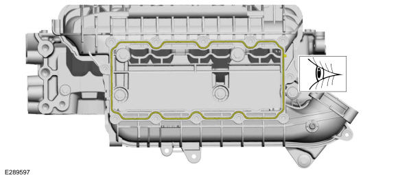
NOTE: The bolts remain captured in the intake manifold.
Loosen the bolts and remove the intake manifold.
 |
-
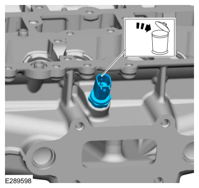
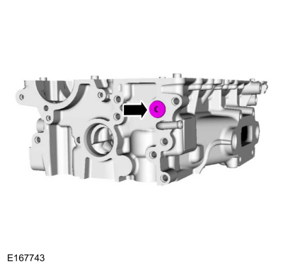
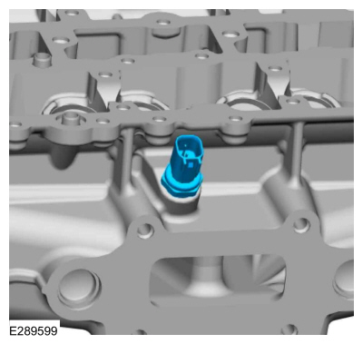
Remove and discard the CHT sensor.
 |
-
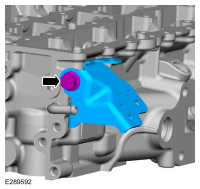
Remove the bolt and the bracket.
 |
-
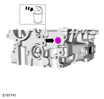
Remove the cylinder head plug and discard.
 |
-
NOTICE: Only use hand tools when removing or installing the spark plugs, or damage can occur to the cylinder head or spark plug.
NOTICE: If a spark plug is dropped, internal damage may result and the spark plug must be discarded. The use of a damaged spark plug may cause cylinder misfire resulting in engine damage.
NOTE: Use compressed air to remove any foreign material in the spark plug well before removing the spark plugs.
Remove the spark plugs.
 |
-
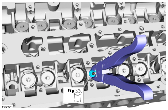
NOTE: Use a small screwdriver and multi-purpose grease to remove the valve collets.
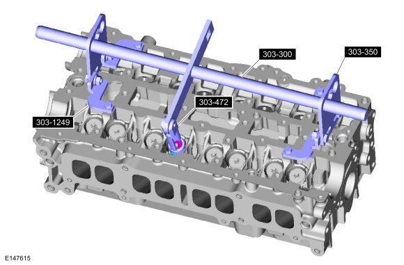
Using the special tools, remove the valve collets, valve spring retainers and the valve springs.
Use Special Service Tool: 303-300 (T87C-6565-A) Set, Valve Spring Compressor. , 303-350 (T89P-6565-A) Compressor, Valve Spring. , 303-472 (T94P-6565-AH) Adapter, Valve Spring Compressor. , 303-1249 Valve Spring Compressor.
Material: Motorcraft® Multi-Purpose Grease Spray / XL-5-A (ESB-M1C93-B)
 |
-
Inspect and install new parts, as necessary.
 |
-
NOTE: Use valve stem seal pliers (such as BeTooll HW0107 or equivalent).
-
Use commercially available valve stem seal pliers to remove the valve stem seal.
-
Discard the valve stem seal.
-
Use commercially available valve stem seal pliers to remove the valve stem seal.
 |
-
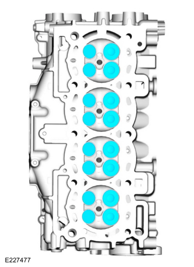
NOTE: Note the location of the valves if they are to be reused.
Remove the intake and exhaust valves.
 |
-
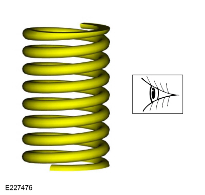
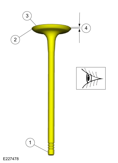
NOTE: Install new parts, as necessary.
-
The end of the stem for grooves or scoring.
-
The valve face and the edge for pits, grooves or scores.
-
The valve head for signs of burning, erosion, warpage and cracking.
-
The valve margin for wear.
-
The end of the stem for grooves or scoring.
 |
ASSEMBLY
-
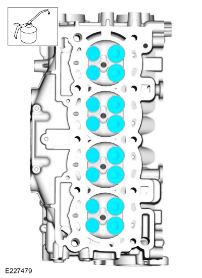
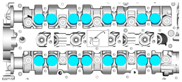
NOTE: If installing the original valves, make sure the valves are installed in the same position from which they were removed. Coat the valve stems with clean engine oil.
Lubricate and install the intake and exhaust valves.
Material: Engine Oil - SAE 5W-20 - Synthetic Blend Motor Oil / XO-5W20-Q1SP (WSS-M2C945-B1)
 |
-
NOTE: Use valve stem seal pliers (such as BeTooll HW0107 or equivalent).
-
Lubricate the valve stem seal with clean engine oil.
Material: Engine Oil - SAE 5W-20 - Synthetic Blend Motor Oil / XO-5W20-Q1SP (WSS-M2C945-B1)
-
Use commercially available valve stem seal pliers to install the valve stem seal.
-
Lubricate the valve stem seal with clean engine oil.
 |
-
NOTE: Use a small screwdriver and multi-purpose grease to install the valve collets.
Using the special tools, install the valve springs, valve spring retainers and the valve collets.
Use Special Service Tool: 303-300 (T87C-6565-A) Set, Valve Spring Compressor. , 303-350 (T89P-6565-A) Compressor, Valve Spring. , 303-472 (T94P-6565-AH) Adapter, Valve Spring Compressor. , 303-1249 Valve Spring Compressor.
Material: Motorcraft® Multi-Purpose Grease Spray / XL-5-A (ESB-M1C93-B)
 |
-
NOTICE: Only use hand tools when removing or installing the spark plugs, or damage can occur to the cylinder head or spark plug.
Install the spark plugs.
Torque: 115 lb.in (13 Nm)
 |
-
Install the cylinder head plug.
Torque: 21 lb.ft (29 Nm)
 |
-
Install the bracket and the bolt.
Torque: 17 lb.ft (23 Nm)
 |
-
Install a new CHT sensor.
Torque: 89 lb.in (10 Nm)
 |
-
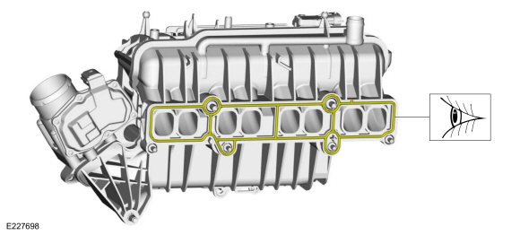
Visually inspect the intake manifold gasket for nicks,
cuts and abrasions. If these conditions are not present, the gaskets may
be re-used.
 |
-
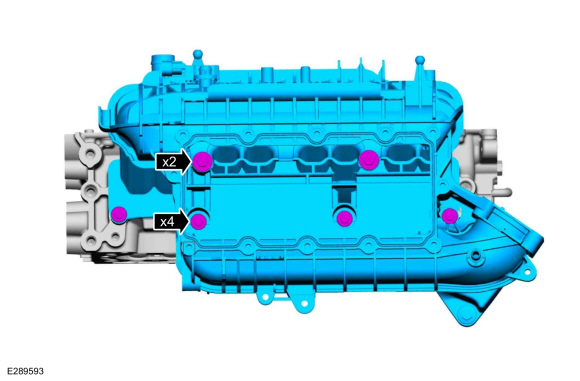
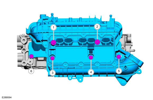
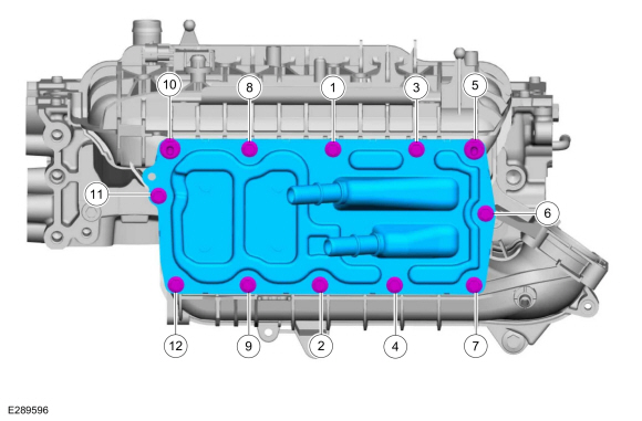
NOTE: Apply threadlock 262 to the intake manifold bolt threads.
Install the intake manifold and tighten the bolts in sequence shown.
Material: Motorcraft® Threadlock 262 / TA-26 (WSK-M2G351-A6)
Torque:
Stage 1: Tighten bolts 1 and 2 to: : 18 lb.in (2 Nm)
Stage 2: Tighten bolts 3 and 4 to: : 18 lb.in (2 Nm)
Stage 3: Tighten bolts 1 and 2 to: : 159 lb.in (18 Nm)
Stage 4: Tighten bolts 3, 4, 5 and 6 to: : 89 lb.in (10 Nm)
Stage 5: Retighten bolts 1 and 2 to: : 159 lb.in (18 Nm)
Stage 6: Retighten bolts 3, 4, 5 and 6 to: : 89 lb.in (10 Nm)
 |
-
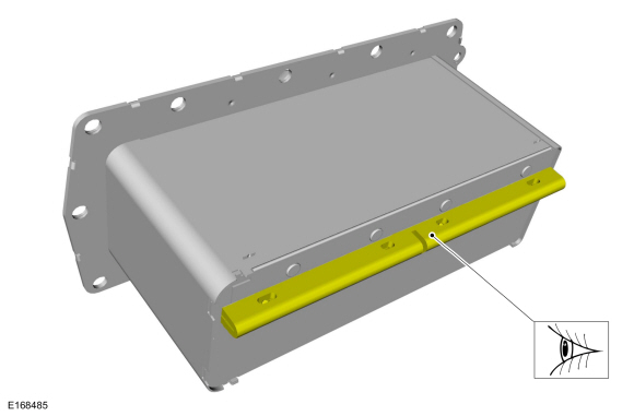
Verify that the CAC seal remains correctly located.
 |
-
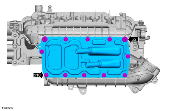
- Install the CAC, the bolts and the stud bolts.
-
Hand tighten bolts 7 and 10.
-
Hand tighten the remaining bolts.
-
Tighten the bolts and the stud bolts.
Torque: 89 lb.in (10 Nm)
 |
-
Lubricate with clean engine oil and install the valve tappets.
Material: Engine Oil - SAE 5W-20 - Synthetic Blend Motor Oil / XO-5W20-Q1SP (WSS-M2C945-B1)
 |
-
NOTICE: Failure to position the cylinder head on wooden blocks may cause cylinder head damage.
NOTE: Make sure that the valves are clear of the wooden blocks.
Position the cylinder head on wooden blocks.
Use the General Equipment: Wooden Block
-
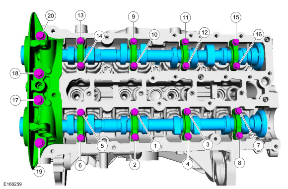
NOTICE: Failure to follow the camshaft tightening procedure can result in damage to the camshafts.
NOTICE: Make sure that the camshafts and camshaft bearing caps are installed in their original locations or damage to the engine may occur.
NOTE: Make sure that the mating faces are clean and free of foreign material.
NOTE: Apply clean engine oil to the bearing surfaces of the camshafts, camshaft bearing caps and the VCT bridge.
-
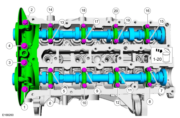
Tighten the bolts evenly, half a turn at a time, until the camshaft bearing caps and the VCT bridge are seated against the cylinder head.
Material: Engine Oil - SAE 5W-20 - Synthetic Blend Motor Oil / XO-5W20-Q1SP (WSS-M2C945-B1)
Torque:
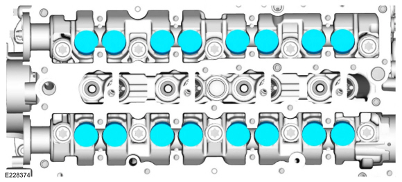
Stage 1: Tighten bolts 1 through 16 to: : 62 lb.in (7 Nm)
Stage 2: Tighten bolts 17 through 20 to: : 89 lb.in (10 Nm)
Stage 3: Tighten bolts 1 through 16 an additional: : 45 °
Stage 4: Tighten bolts 17 and 18 an additional: : 70 °
Stage 5: Tighten bolts 19 and 20 an additional: : 53 °
-
Tighten the bolts evenly, half a turn at a time, until the camshaft bearing caps and the VCT bridge are seated against the cylinder head.
 |
-
-
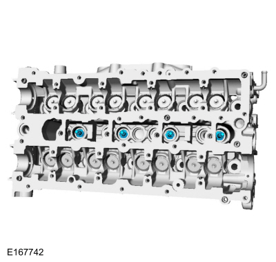
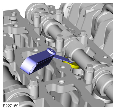
Using the flats of the camshaft, rotate the camshaft
to place the cam lobe at base circle, with the lobe pointed away from
the tappet.
-
Use a feeler gauge to measure the clearance of each valve and record its location.
Use the General Equipment: Feeler Gauge
-
Repeat to measure all of the lobe/tappet clearances.
-
Using the flats of the camshaft, rotate the camshaft
to place the cam lobe at base circle, with the lobe pointed away from
the tappet.
 |
-
NOTE: Select tappets using this formula: ideal tappet thickness = measured clearance + the existing tappet thickness - nominal clearance. Select the closest tappet size to the ideal tappet thickness available and mark the installation location.
NOTE: The nominal clearance is 0.0112 in (.285 mm) for intake and 0.0167 in (.425 mm) for exhaust.
NOTE: The acceptable clearances after being fully installed is 0.009–0.013 in (.24–.33 mm) for intake and 0.015–0.019 in (.38–.47 mm) for exhaust.
-
NOTICE: Failure to follow the camshaft loosening procedure can result in damage to the camshafts.
NOTE: Note the location and orientation of each camshaft bearing cap and the position of the camshaft lobes on the No. 1 cylinder for installation reference.
-
Loosen the camshaft bearing caps 2 turns at a time
until all tension is released from the camshaft bearing caps in sequence
shown.
-
Remove the bolts and the camshaft caps.
-
Remove the camshafts.
-
Discard the bolts.
-
Loosen the camshaft bearing caps 2 turns at a time
until all tension is released from the camshaft bearing caps in sequence
shown.
 |

 Piston. Disassembly and Assembly of Subassemblies
Materials
Name
Specification
Engine Oil - SAE 5W-20 - Synthetic Blend Motor OilXO-5W20-Q1SP
WSS-M2C945-B1
DISASSEMBLY
Remove and discard the piston rings...
Other information:
Ford Fusion 2013–2020 Service Manual: About this Manual. Description and Operation
Introduction WARNING: Before beginning any service procedure in this manual, refer to health and safety warnings in section 100-00 General Information. Failure to follow this instruction may result in serious personal injury. For additional information, refer to: Health and Safety Precautions (100-00 General Information, Description and Operation)...
Ford Fusion 2013–2020 Service Manual: Torque Converter Clutch (TCC). Diagnosis and Testing
For TCC operation, REFER to: Transmission Description - System Operation and Component Description (307-01A Automatic Transmission - 6-Speed Automatic Transmission – 6F35, Description and Operation). Symptom Chart Symptom Possible Sources Action TCC does not apply TCC solenoid filter screen blocked INSTALL a new TCC sol..
Categories
- Manuals Home
- 2nd Generation Ford Fusion Owners Manual
- 2nd Generation Ford Fusion Service Manual
- Automatic Transmission - 6-Speed Automatic Transmission – 6F35
- Powertrain
- Pre-Collision Assist (IF EQUIPPED)
- New on site
- Most important about car
Adjusting the Steering Wheel
WARNING: Do not adjust the steering wheel when your vehicle is moving.
Note: Make sure that you are sitting in the correct position.