
Ford Fusion: Automatic High Beam Control
Ford Fusion 2013–2020 Owners Manual / Automatic High Beam Control
- What Is Automatic High Beam Control. Switching Automatic High Beam Control On and Off
- Automatic High Beam Control Indicators. Overriding Automatic High Beam Control
 Ambient Lighting (IF EQUIPPED)
Use the touchscreen to select the
following:
Select the settings option on
the
feature bar.
Select ambient lighting.
Switching Ambient Lighting On
Touch a color once...
 What Is Automatic High Beam Control. Switching Automatic High Beam Control
On and Off
What Is Automatic High Beam Control. Switching Automatic High Beam Control
On and Off
What Is Automatic High Beam Control
The system turns on high beams if it is dark
enough and no other traffic is present. If it
detects an approaching vehicle’s
headlamps or tail lamps, or street lighting
ahead, the system turns the high beams
off...
Other information:
Ford Fusion 2013–2020 Service Manual: Front Seat Cushion Blower Motor. Removal and Installation
Removal All seats Remove the front seat. Refer to: Front Seat (501-10A Front Seats, Removal and Installation). Remove the side shield screws. Remove the side shield. Lift up on the rear of the side shield and pull outward...
Ford Fusion 2013–2020 Service Manual: Intake Air Distribution and Filtering - Overview. Description and Operation
Overview The air intake system cleans intake air with a replaceable, dry-type engine Air Cleaner (ACL) element made of treated, pleated paper. A new Air Cleaner (ACL) element must be installed periodically as scheduled. Engine performance and fuel economy are adversely affected when maximum restriction of the Air Cleaner (ACL) element is reached...
Categories
- Manuals Home
- 2nd Generation Ford Fusion Owners Manual
- 2nd Generation Ford Fusion Service Manual
- Starter Motor. Removal and Installation
- Powertrain
- Electronic Parking Brake (EPB) Service Mode Activation and Deactivation. General Procedures
- New on site
- Most important about car
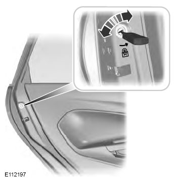
Child Safety Locks
When these locks are set, the rear doors cannot be opened from the inside.

Copyright © 2026 www.fofusion2.com